
Page 51 - Instrumentation Reference Book 3E
P. 51
36 Measurement of flow
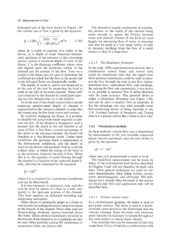
bottomed and of the form shown in Figure 1.49 The channel is usually constructed of concrete,
the volume rate of flow is given by the equation the surface on the inside of the channel being
made smooth to reduce the friction between
water and channel. Flumes of this kind are used
largely for measuring flow of water or sewerage
and may be made in a very large variety of sizes
to measure anything from the flow of a small
where B1 is width of channel, B is width of the stream to that of a large river.
throat, hl is depth of water measured immedi-
ately upstream of the entrance to the converging
section, and h2 is minimum depth of water in the 1.4.1.3 The DutuGator flowmeter
throat. C is the discharge coefficient whose value
will depend upon the particular outline of the In the early 1990s experimentation showed that a
channel and the pattern of the flow. Tests on a combination venturi flume and venturi tube
model of the flume may be used to determine the could be constructed such that the signal from
coefficient provided that the flow in the model and three pressure transducers could be used to meas-
in the full-sized flume are dynamically similar. ure the flow through the tube in any flow regime:
The depths of water hl and h2 are measured as subcritical flow, supercritical flow, and surcharge.
in the case of the weir by measuring the level in By making the flow tube symmetrical, it was shown
wells at the side of the main channel. These wells to be possible to measure flow in either direction
are connected to the channel by small pipes open- with the same accuracy. This patented device is
ing into the channel near or at the bottom. called a DataGator flowmeter (see Figure 1.50),
As in the case of the closed venturi tube a certain and can be used to monitor flow in manholes. It
minimum uninterrupted length of channel is has the advantage over any other portable sewer
required before the venturi is reached, in order that flow-monitoring device of being traceable to the
the stream may be free from waves and vortices. US. National Institute of Standards and Testing
By carefully designing the flume, it is possible since it is a primary device like a flume or flow tube.
to simplify the actual instrument required to indi-
cate the flow. If the channel is designed in such a
manner that the depth in the exit channel at all 1.4.2 Velocitylarea methods
rates of flow is less than a certain percentage of In these methods volume flow rate is determined
the depth in the entrance channel, the flume will by measurement of the two variables concerned
function as a free-discharge outlet. Under these (mean velocity and head), since the rate of flow is
conditions, the upstream depth is independent of given by the equation
the downstream conditions, and the depth of
water in the throat will maintain itself at a certain
critical value, at which the energy of the water is
at the minimum whatever the rate of flow. When
this is so, the quantity of water flowing through where area A is proportional to head or level.
the channel is a function of the upstream depth hl The head/level measurement can be made by
only, and may be expressed by the equation: many of the conventional level devices described
in Chapter 5 and will not therefore be dealt with
Q = kh;l2 here. Three general techniques are used for vel-
ocity measurement, these being turbine current
meter, electromagnetic, and ultrasonic. The tech-
where k is a constant for a particular installation niques have already been discussed in the section
and can be determined. on closed pipe flow and application only will be
It is now necessary to measure Iq only, and this described here.
may be done by means of a float in a well, con-
nected to the upstream portion of the channel.
This float operates an indicated recording and 1.4.2.1 Turbine current meter
integrating instrument.
Other means of sensing the height in a flume or In a current-meter gauging, the meter is used to
weir include up-looking ultrasonic sensors mounted give point velocity. The meter is sited in a prede-
in the bottom of the channel. More often used are termined cross-section in the flowstream and the
down-looking ultrasonic sensors mounted above velocity obtained. Since the meter only measures
the flume. Direct pressure transducers mounted at point velocity it is necessary to sample throughout
the bottom of the channel or in a standpipe can also the cross-section to obtain mean velocity.
be used. Other methods, such as RF Admittance or The velocities that can be measured in this way
capacitance slides, are used as well. range from 0.03 to 3.0 mJs for a turbine meter with