
Page 52 - Instrumentation Reference Book 3E
P. 52
Point velocity measurement 37
a propeller of 50 mm diameter. The disadvantage improve the accuracy of the signal. Recently,
of a current-meter gauging is that it is a point and clamp-on transit-time flow sensors have been
not a continuous measurement of discharge. adapted to work directly on the high-purity tub-
ing used in the semiconductor manufacturing
industry and in the pharmaceutical industry. Cor-
1.4.2.2 Electromagnetic method relation flowmeters have also been constructed
In this technique Faraday's law of electromag- using these new techniques.
netic induction is utilized in the same way as for
closed-pipe flow measurement (Section 1.3.4.1). 1.4.3 Dilution gauging
That is, E 'K BIV, where E is e.m.f. generated, This technique is covered in detail in the section
B is magnetic field strength, 1 is width of river or on flow calibration but basically the principle
channel in meters, and Vis average velocity of the involves injecting a tracer element such as brine,
flowstream. salt, or radioactive solution and estimating the
This equation only applies if the bed of the
channel is insulated, similar to the requirement degree of dilution caused by the flowing liquid.
for pipe flowmeters. In practice it is costly to
insulate a riverbed and where this cannot be done, 1.5 Point velocity measurement
riverbed conductivity has to be measured to com-
pensate for the resultant signal attenuation. It is often desirable in flow studies and survey
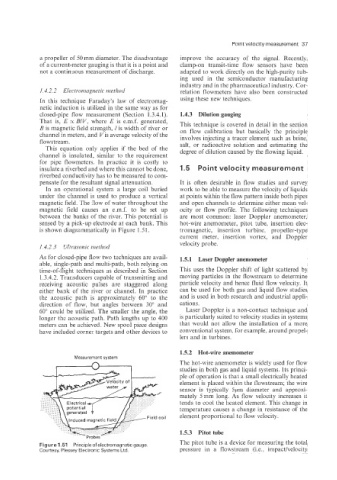
In an operational system a large coil buried work to be able to measure the velocity of liquids
under the channel is used to produce a vertical at points within the flow pattern inside both pipes
magnetic field. The OW of water throughout the and open channels to determine either mean vel-
magnetic field causes an e.m.f. to be set up ocity or flow profile. The following techniques
between rhe banks of the river. This potential is are most common: laser Doppler anemometer:
sensed by a pick-up electrode at each bank. This hot-wire anemometer, pitot tube, insertion elec-
is shown diagrammatically in Figure 1.5 1. tromagnetic, insertion turbine, propeller-type
current meter, insertion vortex, and Doppler
velocity probe.
1.4.2.3 Ultrasonic method
As for closed-pipe flow two techniques are avail- 1.5.1 Laser Doppler anemometer
able, single-path and multi-path, both relying on
time-of-flight techniques as described in Section This uses the Doppler shift of light scattered by
1.3.4.2. Transducers capable of transmitting and moving particles in the flowstream to determine
receiving acoustic pulses are staggered along particle velocity and hence fluid flow velocity. It
either bank of the river or channel. In practice can be used for both gas and liquid flow studies
the acoustic path is approximately 60" to the and is used in both research and industrial appli-
direction of flow, but angles between 30" and cations.
60" could be utilized. The smaller the angle, the Laser Doppler is a non-contact technique and
longer the acoustic path. Path lengths up to 400 is particularly suited to velocity studies in systems
meters can be achieved. New spool piece designs that would not allow the installation of a more
have included corner targets and other devices to conventional system, for example, around propel-
lers and in turbines.
1.5.2 Hot-wire anemometer
Measurement system
A The hot-wire anemometer is widely used for flow
studies in both gas and liquid systems. Its princi-
ple of operation is that a small electrically heated
element is placed within the flowstream; the wire
sensor is typically 5pm diameter and approxi-
mately 5mm long. As flow velocity increases ii
tends to cool the heated element. This change in
temperature causes a change in resistance of the
element proportional to flow velocity.
1.5.3 Pitot tube
Figure 1.511 Principle of electromagnetic gauge The pitot tube is a device for measuring the total
Courtesy, Plessey Electronic Systems Ltd. pressure in a flowstream (i.e., impacthelocity