
Page 49 - Instrumentation Reference Book 3E
P. 49
34 Measurement of flow
Figure 1.45 Rectangular notch, showing top and
bottom of contraction.
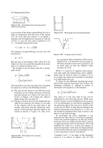
cross-section of the stream approaching the weir is Figure 1.47 Rectangular notch, showing side plates.
large in comparison with the area of the stream
over the weir, then the velocity VI at section 1
upstream can be neglected in comparison with the
velocity V2 over the weir, and in equation (1.17)
VI = 0 and the equation becomes:
V: =2gh or V2 = a
The quantity of liquid flowing over the weir will
be given by: Figure 1.48 Triangular notch (V-notch).
Q=A2V2
ever, produces side-contraction of the stream.
But the area of the stream is BH, where His the Therefore B1 = B should be at least equal to
depth over the weir and B the breadth of the weir, 4H when the side-contraction is equal to 0.1 H
and 12 is a definite fraction of H. on both sides, so that the effective width
By calculus it can be shown that for a rectan- becomes B-0.2H.
gular notch When it is required to suppress side-contrac-
tion and make the measurement more reliable,
(1.46) plates may be fitted as shown in Figure 1.47 so
as to make the stream move parallel to the plates
2 as it approaches the weir.
= -Bdmm3/s (1.47) To allow for the difference between the actual
3
rate of flow and the theoretical rate of flow, the
The actual flow over the weir is less than that given discharge coefficient C, defined as before, is
by equation (1.45) for the following reasons: introduced and equation (1.46) becomes:
(a) The area of the stream is not BH but some-
thing less, for the stream contracts at both the Q = CBdmm3/s (1.48)
top and bottom as it flows over the weir as
shown in Figure 1.46 making the effective The value of C will vary with H and will be
depth at the weir less than H. influenced by the following factors, which must
(b) Owing to friction between the liquid and the remain constant in any installation if its accuracy
sides of the channel, the velocity at the sides is to be maintained: (a) the relative sharpness of
of the channel will be less than that at the the upstream edge of the weir crest, (b) the width
middle. This effect may be reduced by mak- of the weir sill. Both of these factors influence the
ing the notch narrower than the width of the bottom-contraction and influence C, so the weir
stream as shown in Figure 1.47. This, how- sill should be inspected from time to time to see
that it is free from damage.
In developing the above equations it was
assumed that the velocity of the liquid upstream
of the weir could be neglected. As the rate of flow
increases, this is no longer possible and a velocity
of approach factor must be introduced. This will
influence the value of C, and as the velocity of
approach increases it will cause the observed head
to become less than the true or total head so that
a correcting factor must be introduced.
Figure 1.46 Rectangular notch, showing Triangular notch If the angle of the triangular
side-contraction. notch is 0 as shown in Figure 1.48, B=2H