Page 53 - Instrumentation Reference Book 3E
P. 53

38  Measurement of flow

           Sfafic           I’                    pressure and static pressure) and the principle of
           presgure-Yn]                           operation is as follows.
           taPPml           !I                      If a tube is placed with its open end facing into
                                                  the  flowstream  (Figure  1.52)  then  the  fluid
                                                  impinging on the open end will be brought to rest
                                                  and  its  kinetic  energy  converted  into  pressure
                                                  energy. The pressure build-up in the tube will be
                                                  greater than that in the free stream by an amount
                                                  termed the “impact pressure.” If the static pressure
                                                  is  also  measured,  the  differential  pressure
                                                  between that measured by  the pitot tube and the
         Figure 1.52  Single hole pitot tube.     static  pressure will  be  a  measure  of  the  impact
                                                  pressure and therefore the velocity of the stream.
                                                  In  equation  (1.15) h  the  pressure differential or
                                                  impact  pressure  developed  is  given   by
                                                  h = (V2212g) - (V;/2g) where  V, = 0.  Therefore,
                                                  h = - V:/2g, Le.,  the pressure increases by  V:/2g.
                                                  The negative sign indicates that it is an increase in
                                                  pressure and not a decrease.
                                                    Increase in head:
                                                      h = V:/2g  or  V: = 2gh  Le.  VI = &@$
                                                                                    (1.51)
                                                  However, since this is an intrusive device not all
                                                  of the flowstream will be brought  to rest on the
                                                  impact  post; some will  be  deflected round  it. A
                                                  coefficient C is introduced to compensate for this
                                                  and equation (1.50) becomes:
                                                      VI = c   m                    (1.52)
                                                  If the pitot tube is to be used as a permanent device
                                                  for measuring the flow in a pipeline the relation-
                                                  ship between the velocity at the point of its location
                                                  to the mean velocity must be determined. This is
                                                  achieved  by  traversing  the  pipe  and  sampling
                                                  velocity at several points in the pipe, thereby deter-
                                                  mining flow profile and mean velocity.
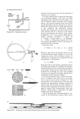
                                                    For more permanent types of pitot-tube instal-
                                                  lation a multiport  pitot  tube (such as an Annu-
                                                  bar@) may be used as shown in Figure l .53. The
                                                  pressure holes are located in such a way that they
                                                  measure  the  representative  dynamic pressure  of
                                                  equal annuli. The dynamic pressure obtained  at
                                                  the four holes facing into the stream is then aver-
                                                  aged by means of the “interpolating” inner tube
                                                  (Figure  1.53(b)), which is connected to the high-
                                                  pressure side of the manometer.
                                                    The low-pressure side of the manometer is con-
                                                  nected  to the  downstream  element which meas-


          Figure 1.53  The Annubar, courtesy, Dietrich Standard Division of Emerson Process Measurement.
   48   49   50   51   52   53   54   55   56   57   58