
Page 58 - Instrumentation Reference Book 3E
P. 58
Further reading 43
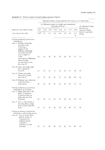
Appendix '1.1 Minimum lengths of straight pipeline upstream of device"
Minimum number of pipe diametersfor Cases A to F listed below
(a) Minirnuin length of straight pipe immediately
upstream of device (b) Minimunz length
- between first
Diaineter r,atio dlD less than: 0.22 0.32 0.45 0.55 0.63 0.7 0.77 0.84 upstream fitting
and next upstream
Area ratio iz less than: 0.05' 0.1 0.2 0.3 0.4 0.5 0.6 0.7 fitting
X
Fittings producing syiizinetiicul
disturbai~ces
Case A Reducer (reducing
not more than
0.5D over a
length of 30)
Enlarger (enlarging
not more than 20
over a length of
1.5D) 16 16 18 20 23 26 29 33 13
Any pressure difference
device having
an area ratio in not
less than 0.3
Cme B. Gate valve fully open
(for a closed see
Case H) 12 12 12 13 16 20 27 38 10
Case c Globe vaive fully
open (for closed
see Case J) 18 18 20 23 27 32 40 49 16
Case D. Reducer (any reduction
including from a
large space) 25 25 25 25 25 26 29 33 13
Fir rings producing asyiiziiietrical
disturbances in one plune
Cme E. Single bend up io 90",
elbow, Y-junction.
T-junction (flow in
either but not both
branches) 10 10 13 16 22 29 41 56 15
Case F. Two or more bends in
the same plane. single
bend of more than 90",
swan 14 15 18 22 28 36 46 57 18
Fittings producing usynmietvical
disturbances and swirling niotion
Case Gt. Two or more bends.
elbows, loops, or
K-junctions in
different planes,
T-junction
with flow in both
branches 34 35 38 44 52 63 76 89 32