
Page 55 - Instrumentation Reference Book 3E
P. 55
40 Measurement of flow
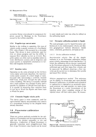
Tracer injection point Sample point
(Tracer concentration C, injection rate all (Tracer concentration C,)
-
Open channel or pipe
Flow Q2- -
A
'-, Figure 1.57 Dilutiongauging
If Q2> > Q1 by tracer injection.
correction factor is introduced to compensate for in open vessels and water can often be utilized as
errors caused by blockage in the flowstream the calibrating liquid.
caused by the turbine assembly.
1.6.1 Flowmeter calibration methods for liquids
1.5.6 Propeller-type current meter The main principles used for liquid flowmeter cali-
Similar to the turbine in operation, this type of bration are in situ: insertion-point velocity and dilu-
velocity probe typically consists of a five-bladed tion gauging/tracer method; laboratory: master
PVC rotor (Figure 1.56) mounted in a shrouded meter, volumetric, gravimetric, and pipe prover.
frame. This device is most commonly used for
river or stream gauging and has the ability to 1.6.1.1 In-situ calibration methods
measure flow velocities as low as 2.5cmls. Pro-
peller meters are often used as mainline meters in Insertion-point velocity One of the simpler
water distribution systems and in irrigation and methods of in situ flowmeter calibration utilizes
canal systems as inexpensive alternatives to tur- point-velocity measuring devices (see Section 1.5)
bine and magnetic flowmeters. where the calibration device chosen is positioned
in the flowstream adjacent to the flowmeter being
calibrated and such that mean flow velocity can
1.5.7 Insertion vortex be measured. In difficult situations a flow tra-
verse can be carried out to determine flow profile
Operating on the same principle as the full-bore and mean flow velocity.
vortex meter previously described, the insertion-
vortex meter consists of a short length of stain-
less-steel tube surrounding a centrally situated Dilution gaugingltracer method This technique
bluff body. Fluid flow through the tube causes can be applied to closed-pipe and open-channel
vortex shedding. The device is normally inserted flowmeter calibration. A suitable tracer (chemical
into a main pipeline via a flanged T-piece and is or radioactive) is injected at an accurately meas-
suitable for pipelines of 200 mm bore and above. ured constant rate and samples are taken from
It is capable of measuring flow velocities from the flowstream at a point downstream of the
0.1 m/s up to 20 m/s for liquids and from 1 mls
to 40 m/s for gases. injection point where complete mixing of the
injected tracer will have taken place. By measur-
1.5.8 Ultrasonic Doppler velocity probe
This device again is more commonly used for
Flow control
open-channel velocity measurement and consists valve
of a streamlined housing for the Doppler meter
already described.
1.6 Flowmeter calibration
methods
There are various methods available for the cali-
bration of flowmeters and the requirement can be
split into two distinct categories: in situ and
laboratory. Calibration of liquid flowmeters is
generally somewhat more straightforward than Figure 1.58 Flowmetercalibration by weighing
that of gas flowmeters since liquids can be stored Courtesy, British Standards Inst,tution