
Page 50 - Instrumentation Reference Book 3E
P. 50
Flow in open channels 35
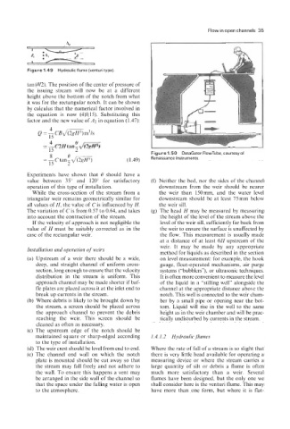
Figure 1.49 Hydraulic flume (venturi type).
tan (0/2). The position of the center of pressure of
the issuing stream will now be at a different
height above the bottom of the notch from what
it was for the rectangular notch. It can be shown
by calculus that the numerical factor involved in
the equation is now (4)/(15). Substituting this
factor and the new value of A2 in equation (1.47):
0
= 5 C2H tan? &= I --
15 Figure 1.50 DataGator FlowTube, courtesyof
8
0
= - c tanZ d m (1.49) Renaissance Instruments.
15
Experiments have shown that 0 should have a
value between 35” and 120” for satisfactory (f) Neither the bed, nor the sides of the channel
operation of this type of installation. downstream from the weir should be nearer
While the cross-section of the stream from a the weir than 150mm, and the water level
triangular weir remains geometrically similar for downstream should be at least 75mm below
all values of H, the value of C is influenced by H. the weir sill.
The variation of Cis from 0.57 to 0.64, and takes (g) The head H may be measured by measuring
into account the contraction of the stream. the height of the level of the stream above the
If the velocity of approach is not negligible the level of the weir sill, sufficiently far back from
value of H must be suitably corrected as in the the weir to ensure the surface is unaffected by
case of the rectangular weir. the flow. This measurement is usually made
at a distance of at least 6H upstream of the
weir. It may be made by any appropriate
Installation and operation of weirs
method for liquids as described in the section
(a) Upstream of a weir there should be a wide, on level measurement: for example, the hook
deep, and straight channel of uniform cross- gauge, float-operated mechanisms, air purge
section, long enough to ensure that the velocity systems (“bubblers”), or ultrasonic techniques.
distribution in the stream is uniform. This It is often more convenient to measure the level
approach channel may be made shorter if baf- of the liquid in a “stilling well” alongside the
fle plates are placed across it at the inlet end to channel at the appropriate distance above the
break up currents in the stream. notch. This well is connected to the weir cham-
(b) Where debris is likely to be brought down by ber by a small pipe or opening near the bot-
the stream, a screen should be placed across tom. Liquid will rise in the well to the same
the approach channel to prevent the debris height as in the weir chamber and will be prac-
reaching the weir. This screen should be tically undisturbed by currents in the stream.
cleaned as often as necessary.
(c) The upstream edge of the notch should be
maintained square or sharp-edged according 1.4.1.2 Hydraulic flumes
to the type of installation.
(d) The weir crest should be level from end to end. Where the rate of fall of a stream is so slight that
(e) The channel end wall on which the notch there is very little head available for operating a
plate is mounted should be cut away so that measuring device or where the stream carries a
the stream may fall freely and not adhere to large quantity of silt or debris a flume is often
the wall. To ensure this happens a vent may much more satisfactory than a weir. Several
be arranged in the side wall of the channel so flumes have been designed, but the only one we
that the space under the falling water is open shall consider here is the venturi flume. This may
to the atmosphere. have more than one form, but where it is flat-