
Page 44 - Instrumentation Reference Book 3E
P. 44
Fluid flow in closed pipes 29
knowledge of each installation, and in situ cali- the vortices. Various methods exist, the more
bration is desirable. popular techniques being as follows:
1.3.4.3 Oscilbtory “Fluidic” Jlowmetevs (a) Ultrasonic. Where the vortices pass through
an ultrasonic beam and cause refraction of
The operating principle of flowmeters in this cate- this beam resulting in modulation of the
gory is based on the fact that if an obstruction of beam amplitude.
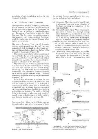
known geometry is placed in the flowstream the (b) Thermal (Figure 1.37(e)). Where a theimistor-
fluid will start to oscillate in a predictable man- type sensor is located in a through passage
ner. The degree of oscillation is related to fluid across the bluff body an6 behind its face. The
flow rate. The three main types of flowmeter in heated thermistor will sense alternating vortices
this category are: .vortex-shedding flowmeter, due to the cooling effect caused by their pas-
swirl flowmeter, and the several Coanda effect sage, and an electrical ?&e output is obtained.
meters now avaiiable. (c) Oscillating disc. Sensing ports on both sides
The vortex jlownzetev This type of flowmeter of the flow element cause a small disc to
operates on the principle that if a bluff (i.e., non- oscillate. A variable-reluctance pick-up detects
streamlined) body is placed in a flowstream vor- the disc’s oscillation. This type is particularly
tices will be detached or shed from the body. The suited to steam or wet-gas flow.
principle is illustrated in Figure 1.36. (d) Capacitance. Metal diaphragms are welded
The vortices are shed alternately to each side of on opposite sides of the bluff body, the small
the bluff body, the rate of shedding being directly gaps between the diaphragms and the body
proportional to flow velocity. If this body is fitted being filled with oil. Interconnecting ports
centrally into a pipeline the vortex-shedding fre-
quency is a measure of the flow rate.
Any biuff body can be used to generate vortices
in a flowstream, but for these vortices to be reg-
ular and well defined requires careful design.
Essential.lp, the body must be non-streamlined,
symmetrical, and capable of generating vortices
for a wide Reynolds number range. The most Flow direction
commonly adopted bluff body designs are shown ____)
in Figure 1.37.
These designs all attempt to enhance the vor-
tex-shedding effect to ensure regularity or sim-
plify the detection technique. If the design (d) is
considered it will be noted that a second non- (C)
streamlined body is placed just downstream of
the vortex-shedding body. Its effect is to reinforce
and stabiiize the shedding. The width of the bluff Thermal P
body is determined by pipe size, and a rule-of- sensor
thumb guide is that the ratio of body width to
pipe diaineter should not be less than 0.2.
Sensing methods Once the bluff-body type has
been selected we must adopt a technique to detect
V pick-up
777m7z2T77mzz
(f)
/ I I Figure 1.37 (a)-(d) Bluff bodyshapes. (e) Thermal
Bluff body V.,iSX Pipewall
sensor. Courtesy, Actaris Neptune Ltd. (f) Shuttle ball
Figure 1.36 Vortexstiedding. sensor. Courtesy, Actaris Neptune Ltd.