
Page 41 - Instrumentation Reference Book 3E
P. 41
26 Measurement of flow
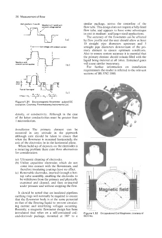
IdeA wmform I' similar package, across the centerline of the
Waveform of 1 and 8 with
flow tube. This design does not require a fully-lined
flow tube, and appears to have some advantages
in cost in medium- and larger-sized applications.
The accuracy of the flowmeter can be affected
(a) by flow profile and the user should allow at least
10 straight pipe diameters upstream and 5
straight pipe diameters downstream of the pri-
mary element to ensure optimum conditions.
Also to ensure system accuracy it is essential that
the primary element should remain filled with the
liquid being metered at all times. Entrained gases
will cause similar inaccuracy.
For further information on installation
I1
I requirements the reader is referred to the relevant
v. I
sections of BS 5792 1980.
v2 (C)
(2 +Z)
IZ +Zl
-
Vflow- IV, -(l 2-2
1
)-(VI
2 2
Figure 1.31 Electromagnetic flowmeter-pulsed DC
excitation. Courtesy, Flowmetering Instruments Ltd.
density, or conductivity. Although in the case
of the latter conductivities must be greater than
1 micromho/cm.
Installation The primary element can be
mounted in any attitude in the pipework
although care should be taken to ensure that
when the flowmeter is mounted horizontally the
axis of the electrodes be in the horizontal plane.
Where build-up of deposits on the electrodes is
a recurring problem there exist three alternatives
for consideration:
(a) Ultrasonic cleaning of electrodes.
(b) Utilize capacitive electrodes which do not
come into contact with the flowstream, and
therefore insulating coatings have no effect.
(c) Removable electrodes, inserted through a hot-
tap valve assembly, enabling the electrodes to
be withdrawn from the primary and physically
examined and cleaned, and then re-inserted
under pressure and without stopping the flow.
It should be noted that on insulated pipelines
earthing rings will normally be required to ensure
that the flowmeter body is at the same potential
as that of the flouring liquid to prevent circulat-
ing current and interfering voltages occurring.
Recently, a magnetic flowmeter design has been
introduced that relies on a self-contained coil- Figure 1.32 Encapsulated Coil Magmeter, courtesyof
and-electrode package, mounted at 180" to a ISCO Inc.