
Page 36 - Instrumentation Reference Book 3E
P. 36
Fluid flow in closed pipes 21
1.3.3 Rotating mechanical meters for gases medium for the measuring chambers is not solid
but is water or some other suitable liquid.
The principal types to be discussed are positive The instrument is shown in section in Figure
displacement, deflecting vane, rotating vane. and 1.27. It consists of an outer chamber of tinned
turbine. brass plate or Staybrite steel sheeting containing a
rotary portion. This rotating part consists of
1.3.3.1 Positive displacement shaped partitions forming four measuring cham-
bers made of light-gauge tinplate or Staybrite
Three main types of meter come under this heading. steel, balanced about a center spindle so that it
They are diaphragm meter, wet gas meter (liquid can rotate freely. Gas enters by the gas inlet near
sealed drum), and rotary displacement meter. the center and leaves by the outlet pipe at the top
of the outer casing. The measuring chambers are
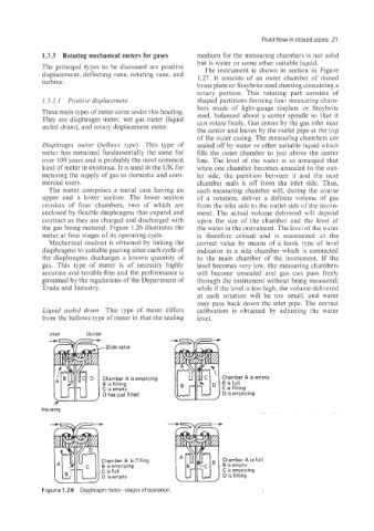
Diaphragm meter (bellows type) This type of sealed off by water or other suitable liquid which
mete; has remained fundamentally the same for fills the outer chamber to just above the center
over 100 years and is probably the most common line. The level of the water is so arranged that
kind of meter in existence. It is used in the UK for when one chamber becomes unsealed to the out-
metering the supply of gas to domestic and com- let side, the partition between it and the next
mercial users. chamber seals it off from the inlet side. Thus,
The meter comprises a metal case having an each measuring chamber will, during the course
upper and a lower section. The lower section of a rotation, deliver a definite volume of gas
consists of four chambers, two of which are from the inlet side to the outlet side of the instru-
enclosed by flexible diaphragms that expand and ment. The actual volume delivered will depend
contract as they are charged and discharged with upon the size of the chamber and the level of
the gas being metered. Figure 1.26 illustrates the the water in the instrument. The level of the water
meter at four stages of its operating cycle. is therefore critical and is maintained at the
Mechanical readout is obtained by linking the correct value by means of a hook type of level
diaphragms to suitable gearing since each cycle of indicator in a side chamber which is connected
the diaphragms discharges a known quantity of to the main chamber of the instrument. If the
gas. This type of meter is of necessity highly level becomes very low, the measuring chambers
accurate and trouble-free and the performance is will become unsealed and gas can pass freely
governed by the regulations of the Department of through the instrument without being measured;
Trade and Industry. while if the level is too high, the volume delivered
at each rotation will be too small, and water
may pass back down the inlet pipe. The correct
Liquid sealed drum This type of meter differs calibration is obtained by adjusting the water
from the bellows type of meter in that the sealing level.
---
Inlet Outlet
-Slide valve
Chamber A is empl :ying Chamber A is empty
B is filling B is full
C is empty C is filling
ci has just filled D is emptying
Housing
Chamber A is filling Chamber A is full
B is empty
C is emptying
D is filling
Figure 1.26 Diaphragm meter-stages of operation.