
Page 35 - Instrumentation Reference Book 3E
P. 35
20 Measurement of flow
between its spindle and the sleeve bearings is
small. The water is directed evenly onto the vanes
by means of guides.
Transmission of the rotation from the under-
gear to the meter register is by means of ceramic
magnetic coupling.
The body of the meter is cast iron, and the
mechanism and body cover is of thermoplastic
injection moulding. The meter causes only small
head loss in operation and is suited for use in
water-distribution mains. It is available in sizes
from 40 mm up to 300 mm, respective maximum
flow rates being 24m3/h and 1540m3/h, with
accuracy of 412 percent over 20:l turn-down
ratio.
1.3.2.6 Turbine meter Bearing
Deflector
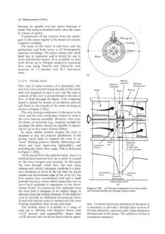
This type of meter consists of a practically fric- ~~~~~~~1 ass~blv (downstream)
tion-free rotor pivoted along the axis of the meter Hanger
tube and designed in such a way that the rate of \
rotation of the rotor is proportional to the rate of
flow of fluid through the meter. This rotational
speed is sensed by means of an electric pick-off
coil fitted to the outside of the meter housing as
shown in Figure 1.25(a).
The only moving component in the meter is the
rotor, and the only component subject to wear is
the rotor bearing assembly. However, with care- 1
ful choice of materials (e.g., tungsten carbide for
bearings) the meter should be capable of operat-
ing for up to five years without failure. I I
In many similar product designs the rotor is
designed so that the pressure distribution of the
process liquid helps to suspend the rotor in an 1
1
“axial” floating position, thereby eliminating end- hub I Clearance
,
Rotor
thrust and wear, improving repeatability, and IrnpingLnt for rotor
extending the linear flow range. This is illustrated annulus A , I to float clear
of any end stops
in Figure 1.25(b). I
As the liquid flows through the meter, there is a
small gradual pressure loss up to point A caused
by the rotor hangers and housing. At this point
the area through which flow can take place
reduces and velocity increases, resulting in a pres-
sure minimum at point B. By the time the liquid
reaches the downstream edge of the rotor (C), the
flow pattern has reestablished itself and a small I balance point
pressure recovery occurs which causes the rotor to Pressure distribution
move hard upstream in opposition to the down- (b)
stream forces. To counteract this upstream force Figure 1.25 (a) Principle of operation of turbine meter.
the rotor hub is designed to be slightly larger in (b) Pressure distribution through turbine meter.
diameter than the outside diameter of the deflector
cone to provide an additional downstream force.
A hydraulic balance point is reached with the rotor
floating completely clear of any end stops. tion. To ensure optimum operation of the meter it
The turbine meter is available in a range of is necessary to provide a straight pipe section of
sizes up to 500mm with linearity better than 10 pipe-diameters upstream and 5 pipe-diameters
10.25 percent and repeatability better than downstream of the meter. The addition of flow is
f0.02 percent and can be bi-directional in opera- sometimes necessary.