
Page 37 - Instrumentation Reference Book 3E
P. 37
22 Measurement of flow
Gas outlet
4
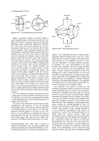
Figure 1.27 Liquid sealeddrumtypegasmeter.
When a partition reaches a position where a
small sealed chamber is formed connected to the
inlet side, there is a greater pressure on the inlet 4J
side than on the outlet side. There will therefore
be a force that moves the partition in an anti- Gas inlet
clockwise direction, and so increases the volume Figure 1.28 Rotarydisplacement meter.
of the chamber. This movement continues until
the chamber is sealed off from the inlet pipe but
opened up to the outlet side, while at the same Figure 1.28. Although the meter is usually man-
time the chamber has become open to the inlet ufactured almost entirely from cast iron, other
gas but sealed off from the outlet side. This pro- materials may be used if desired. The meter basi-
duces continuous rotation. The rotation operates cally consists of two impellers housed in a cas-
a counter which indicates complete rotations and ing and supported on rolling element bearings.
fractions of rotation, and can be calibrated in A clearance of a few thousandths of an inch
actual volume units. The spindle between the between the impellers and the casing prevents
rotor and the counter is usually made of brass wear, with the result that the calibration of the
and passes through a greasepacked gland. The meter remains constant throughout its life. The
friction of this gland, together with the friction leakage rate is only a small fraction of 1 per cent
in the counter gearing, will determine the pressure and this is compensated for in the gearing counter
drop across the meter, which is found to be ratio. Each lobe of the impellers has a scraper tip
almost independent of the speed of rotation. This machined onto its periphery to prevent deposits
friction must be kept as low as possible, for if forming in the measuring chamber. The impellers
there is a large pressure difference between inlet are timed relative to each other by gears fitted to
and outlet sides of the meter, the level of the one or both ends of the impeller shafts.
water in the measuring chambers will be forced The impellers are caused to rotate by the
down, causing errors in the volume delivered; and decrease in pressure which is created at the meter
at low rates of flow the meter will rotate in a jerky outlet following the use of gas by the consumer.
manner. Each time an impeller passes through the vertical
It is very difficult to produce partitions of such position a pocket of gas is momentarily trapped
a shape that the meter delivers accurate amounts between the impeller and the casing. Four pock-
for fractions of a rotation; consequently the meter ets of gas are therefore trapped and expelled dur-
is only approximately correct when fractions of a ing each complete revolution of the index shaft.
rotation are involved. The rotation of the impellers is transmitted to the
The mass of gas delivered will depend upon the meter counter by suitable gearing so that the
temperature and pressure of the gas passing counter reads directly in cubic feet. As the meter
through the meter. The volume of gas is measured records the quantity of gas passing through it
at the inlet pressure of the meter, so if the tem- at the conditions prevailing at the inlet it is
perature and the density of the gas at s.t.p. are necessary to correct the volume indicated by the
known it is not difficult to calculate the mass of meter index for various factors. These are
gas measured. The gas will of course be saturated normally pressure, temperature, and compressibi-
with water vapor and this must be taken into lity. Corrections can be carried out manually if
account in finding the partial pressure of the gas. the conditions within the meter are constant.
Alternatively the correction can be made con-
Rotating-impellev type This type of meter is tinuously and automatically by small mechanical
similar in principle to the rotating-impeller type or electronic computers if conditions within the
meter for liquids and could be described as a two- meter vary continuously and by relatively Large
toothed gear pump. It is shown schematically in amounts. Meters can also drive, through external