
Page 38 - Instrumentation Reference Book 3E
P. 38
Fluid flow in closed pipes 23
gearing, various types of pressure- or tempera- 1.3.3.3 Rotating-vane type
ture-recording devices as required. Anemometers As in the case of the deflecting-
Meters of this type are usually available in pres-
sures up to 60 bar and will measure flow rates from vane type, the force available from gases to pro-
duce the rotation of a vane is considerably less
approximateiy 12 m3/h up to 10,000 m3/h. Within than that available in the measurement of liquids.
these flow rates the meters will have a guaranteed The vanes must therefore be made light or have a
accuracy of * 1 .O percent, over a range of from 5 to large surface area. The rotor as a whole must be
100 percent of maximum capacity. The pressure
drop across the meter at maximum capacity is accurately balanced, and the bearings must be as
friction-free as possible and may be in the form of
always less than 50mmwg. These capacities and a multi-cap or multiple-fan blade design, the
the pressure loss information are for meters operat- speed of rotation being proportional to air speed.
ing at low pressure; the values would be subject to
the effects of gas density at high pressure.
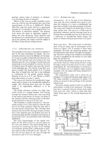
Rotary gas meter The rotary meter is a develop-
ment of the air meter type of anemometer and is
1.3.3.2 DeJZecting-vane type: velometers shown in Figure 1.29. It consists of three main
assemblies: the body, the measuring element, and
The principle of this type of instrument is similar to the multi-point index driven through the intergear-
that of the same instrument for liquids. The con- ing. The lower casing (1) has integral in-line flanges
struction, however, has to be different, for the dens- (2) and is completed by the bonnet (3) with index
ity of a gas is usually considerably less than that of a glass (4) and bezel (5).
liquid. As the force per unit area acting on the vane The measuring element is made up of an inter-
depends upon the rate of change of momentum and nal tubular body (6), which directs the flow of gas
momentum is mass multiplied by velocity, the force through a series of circular ports (7) onto a vaned
will depend upon the density and upon the velocity anemometer (8). The anemometer is carried by a
of the impinging gas. The velocity of gas flow in a pivot (9) which runs in a sapphire-agate bearing
main is usually very much greater (6 to 10 times) assembly (lo), the upper end being steadied by a
than that off liquid flow but this is not sufficient bronze bush (1 1).
to compensate for the greatly reduced density. The multi-pointer index (12) is driven by an
(Density of dry air at 0°C and 760mm is 0.0013 intergear (13) supported between index plates (14).
g/ml while density of water is 1 g/ml.) The index assembly is positioned by pillars (15)
The vane must therefore be considerably larger which are secured to the top flange of the internal
when used for gases or be considerably reduced in tubular body.
weight. The restoring force must also be made The meter casing is made of cast iron whilst the
small if an appreciable deflection is to be anemometer is made from aluminum. The larger
obtained. sizes have a separate internal tubular body made
The simple velometer consists of a light vane from cast iron, with a brass or mild steel skirt
which travels in a shaped channel. Gas flowing which forms part of the overall measuring ele-
through the channel deflects the vane according ment.
to the velocity and density of the gas; the shape of
the channel, and the restoring torque of the hair-
spring attached to the pivot of the vane.
The velometer is usually attached to a “duct jet”
which consists of two tubes placed so that the open
end of one faces upstream while the open end of
the other points downstream. The velometer then
measures the rate of flow through the pair of tubes,
and as this depends upon the lengths and sizes of
connecting pipes and the resistance and location of
the pressure holes, each assembly needs individual
calibration.
The main disadvantages of this simple velo-
meter are the effects of hot or corrosive gases on
the vane and channel. This disadvantage may be
overcome by measuring the flow of air through
the velometer produced by a differential air pres-
sure equal to that produced by the “duct jet.” In
this way the hot gases do not pass through the Figurel.29 Diagrammaticsection ofa rotarygasmeter
instrument, and so it is not damaged. Courtesy, Parkinson & Cowan Compteurs