
Page 43 - Instrumentation Reference Book 3E
P. 43
28 Measurement of flow
Due to the fact that the flowmeter measures
velocity across the center of the pipe it is suscep-
tible to flow profile effects, and care should be
taken to ensure sufficient length of straight pipe
upstream and downstream of the flowtube to
Vc-- minimize such effects. To overcome this problem,
some manufacturers use multiple-beam techniques
/
/ where several chordal velocities are measured and
/
the average computed. However, it is still good
practice to allow for approximately 10 upstream
and 5 downstream diameters of straight pipe. Also
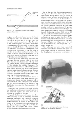
Figure 1.34 Principle of operation time-of-flight since this type of flowmeter relies on transmission
ultrasonic flowmeter. through the flowing medium, fluids with a high
solids or gas-bubble content cannot be metered.
This type of flowmeter can be obtained for use
projects an ultrasonic beam across the liquid on liquids or gases for pipe sizes from 75mm
flowing in a pipe. This ultrasonic pulse is then nominal bore up to 1500mm or more for special
received on the other side of the pipe, where it is applications and it is bi-directional in operation.
converted back to an electronic pulse. The latter Accuracy of better than fl per cent of flow rate
is then received by the “first-arrival” electronics, can be achieved over a flow range of 0.2 to 12
comparing its arrival time with the second pulse meters per second.
received directly. If the two pulses are received at This technique has also been successfully
the same time, the period of time between them applied to open channel and river flow and is also
equates to the time taken for the first pulse to now readily available as a clamp-on flowmeter
travel to its transducer and be converted to ultra- for closed pipes, but accuracy is dependent on
sound, to travel across the flowstream, to be
reconverted back to an electronic pulse, and travel
back to the first-arrival position.
Should the second pulse arrive before the first
one, then the time between pulses is too short.
Then the first-arrival electronics will step down
the voltage to the voltage-controlled oscillator
(VCO), reducing the resulting frequency. The
electronics will continue to reduce voltage to the
VCO in steps, until the first and second pulses are
received at the first-arrival electronics at the same
time. At this point, the periodic time of the
frequency will be the same as the ultrasonic flight
time, plus the electronic delay time.
If, now, a similar electronic circuit is used to
project an ultrasonic pulse in the opposite direc-
tion to that shown, another frequency will be
obtained which, when subtracted from the first,
will give a direct measure of the velocity of the
fluid in the pipe, since the electronic delays will
cancel out. (a) Flexible Conduit
Ceaxial cable \
In practice, the piezoelectric ceramic transdu-
cers used act as both transmitters and receivers of
the ultrasonic signals and thus only one is
required on each side of the pipe.
Typically the flowmeter will consist of a flow-
tube containing a pair of externally mounted,
ultrasonic transducers and a separate electronic
converterltransmitter as shown in Figure 1.35(a).
Transducers may be wetted or non-wetted and
consist of a piezoelectric crystal sized to give
the desired frequency (typically 1-5 MHz for
liquids and 0.2-0.5 MHz for gases). Figure Figure 1.35 (a) Ultrasonic flowmeter. Courtesy,
1.35(b) shows a typical transducer assembly. Sparling Inc. (b) Transducer assembly.