
Page 42 - Instrumentation Reference Book 3E
P. 42
Fluid flow in closed pipes 27
Flowmeters are available in sizes from 32mm The Doppler meter is normally used as an inex-
to 1200mm nominal bore to handle flow veloci- pensive clamp-on flowmeter, the only operational
ties from 0-0.5ds to &lOm/s with accuracy of constraints being that the flowstream must contain
il percent over a 1O:l turndown ratio. discontinuities of some kind (the device will not
monitor clear liquids), and the pipeline must be
1.3.4.2 Ultrasonic flowmeters acoustically transmissive.
Accuracy and repeatability of the Dop-
Ultrasonic flowmeters measure the velocity of a pler meter are somewhat suspect and difficult to
flowing medium by monitoring interaction quantify since its operation is dependent on flow
between the flowstream and an ultrasonic sound profile, particle size, and suspended solids concen-
wave transmitted into or through it. Many tech- tration. However, under ideal conditions and
niques exist, the two most commonly applied given the facility to calibrate in situ accuracies of
being Doppler and transmissive (time of flight). 15 percent should be attainable. This type of
These wiil now be dealt with separately.
flowmeter is most suitable for use as a flow switch
or for flow indication where absolute accuracy is
Dopplerflowmeters These make use of the well- not required.
hewn Doppler effect which states that the fre-
quency of sound changes if its source or reflector
moves relative to the listener or monitor. The Transmissive flowmeters Transmissive devices
magnitude of the frequency change is an indica- differ from Doppler flowmeters in that they rely
tion of the speed of the sound source or sound on transmission of an ultrasonic pulse through
reflector. the flowstream and therefore do not depend on
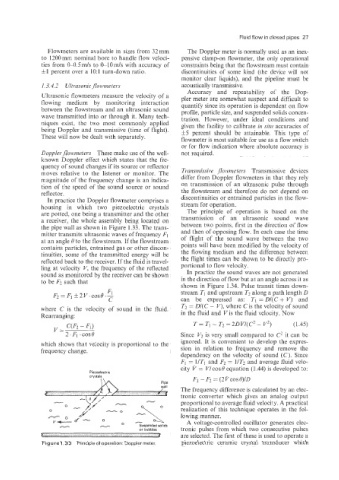
In practice the Doppler flowmeter comprises a discontinuities or entrained particles in the flow-
housing in which two piezoelectric crystals stream for operation.
are potted, one being a transmitter and the other The principle of operation is based on the
a receiver, the whole assembly being located on transmission of an ultrasonic sound wave
the pipe wall as shown in Figure 1.33. The trans- between two points, first in the direction of flow
mitter transmits ultrasonic waves of frequency F1 and then of opposing flow. In each case the time
at an angle 6' to the flowstream. If the flowstream of flight of the sound wave between the two
contains particles, entrained gas or other discon- points will have been modified by the velocity of
tinuities. some of the transmitted energy will be the flowing medium and the difference between
reflected back to the receiver. If the fluid is travel- the flight times can be shown to be directly pro-
ling at veiocity V, the frequency of the reflected portional to flow velocity.
sound as monitored by the receiver can be shown In practice the sound waves are not generated
to be F2 such that in the direction of flow but at an angle across it as
shown in Figure 1.34. Pulse transit times down-
Fl
F2 =Fl ~~V.COS~.- stream TI and upstream T2 along a path length D
C can be expressed as: TI =D/(C+ Vj and
where C is the velocity of sound in the fluid. T2 = D/(C - V), where C is the velocity of sound
Rearranging: in the fluid and Vis the fluid velocity. Now
T = Ti - Tz = 2DV/(C2 - V2) (1.45)
Since V2 is very small compared to C2 it can be
which shows that velocity is proportional to the ignored. It is convenient to develop the expres-
frequency change. sion in relation to frequency and remove the
dependency on the velocity of sound (C). Since
Fl = UT, and F2 = 1IT2 and average fluid velo-
city v = V/ cos 8 equation (1.44) is developed to:
Piezoelectric
crystals
Fi - F2 = (21/~0sB)/D
The frequency difference is calculated by an elec-
tronic converter which gives an analog output
proportional to average fluid velocity. A practical
realization of this technique operates in the fol-
- - lowing manner.
A voltage-controlled oscillator generates elec-
Suspended solids
or bubbles tronic pulses from which two consecutive pulses
are selected. The first of these is used to operate a
Figure 1.33 Principle of operation Doppler meter piezoelectric ceramic crystal transducer which