
Page 31 - Instrumentation Reference Book 3E
P. 31
16 Measurement of flow
element is indicated by several possible means
including a pointer moving over a dial driven
from the measuring element by suitable gearing ”- 20 -
and a magnetically coupled sensor connected to
an electronic indicator or “flow computer.”
The extent of error, defined as the difference
between the indicated quantity and the true quan-
tity and expressed as a percentage of the true
quantity, is dependent on many factors, among
them being:
(a) The amount of clearance between the rotor
and the measuring chamber through which
liquid can pass unmetered.
(b) The amount of torque required to drive the
register. The greater the torque, the greater the
pressure drop across the measuring element,
which in turn determines the leakage rate past
the rotor. This is one reason why electronic
readout devices have become much more com-
mon in recent years, as it eliminates this error
factor.
(c) The viscosity of the liquid to be measured.
Increase in viscosity will also result in
increased pressure drop across the measuring
element, but this is compensated for by the
reduction in flow through the rotor clearances
for a given pressure drop.
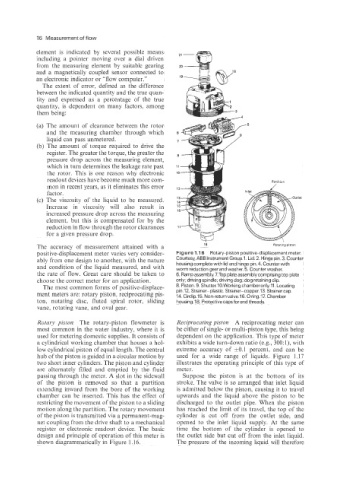
The accuracy of measurement attained with a 18 Rotating PlltU”
positive-displacement meter varies very consider- Figure 1.1 6 Rotary-piston positive-displacement meter.
ably from one design to another, with the nature Courtesy,ABB Instrument Group.1. Lid. 2. Hinge pin. 3. Counter
housing complete with lid and hinge pin. 4. Counter with
and condition of the liquid measured, and with worm reduction gear and washer. 5. Counter washer.
the rate of flow. Great care should be taken to 6. Ramp assembly. 7.Top plate assembly comprising top plate
choose the correct meter for an application. only; driving spindle; driving dog; dog retaining clip.
The most common forms of positive-displace- 8. Piston. 9. Shutter. 10.Working chamber only.11. Locating
ment meters are: rotary piston, reciprocating pis- pin. 12. Strainer-plastic. Strainer-copper. 13. Strainer cap.
14. Circlip.15. Non-return valve. 16.0 ring.17. Chamber
ton, nutating disc, fluted spiral rotor, sliding housing. 18. Protective caps for end threads.
vane, rotating vane, and oval gear.
Rotary piston The rotary-piston flowmeter is Reciprocating piston A reciprocating meter can
most common in the water industry, where it is be either of single- or multi-piston type, this being
used for metering domestic supplies. It consists of dependent on the application. This type of meter
a cylindrical working chamber that houses a hol- exhibits a wide turn-down ratio (e.g., 300:1), with
low cylindrical piston of equal length. The central extreme accuracy of *O.l percent, and can be
hub of the piston is guided in a circular motion by used for a wide range of liquids. Figure 1.17
two short inner cylinders. The piston and cylinder illustrates the operating principle of this type of
are alternately filled and emptied by the fluid meter.
passing through the meter. A slot in the sidewall Suppose the piston is at the bottom of its
of the piston is removed so that a partition stroke. The valve is so arranged that inlet liquid
extending inward from the bore of the working is admitted below the piston, causing it to travel
chamber can be inserted. This has the effect of upwards and the liquid above the piston to be
restricting the movement of the piston to a sliding discharged to the outlet pipe. When the piston
motion along the partition. The rotary movement has reached the limit of its travel, the top of the
of the piston is transmitted via a permanent-mag- cylinder is cut off from the outlet side, and
net coupling from the drive shaft to a mechanical opened to the inlet liquid supply. At the same
register or electronic readout device. The basic time the bottom of the cylinder is opened to
design and principle of operation of this meter is the outlet side but cut off from the inlet liquid.
shown diagrammatically in Figure 1.16. The pressure of the incoming liquid will therefore