
Page 64 - Instrumentation Reference Book 3E
P. 64
Shop-floor viscometers 49
Newtonian fluids is very similar to (2.1 1) and is in so that the viscosity 7 is determined from
fact given by
7 = Mgth/xA (2.16)
2
c = 3 7ra3-Y71(”i) (2.12) Clearly, this technique is only applicable to “stiff”
systems, i.e., liquids of very high viscosity.
where the shear rate y is given by
Y = RoiOo (2.13) 2.4 Shop-floor viscometers
which is (approximately) constant throughout the
test fluid, provided 00 is small (<4”, say). This is A number of ad hoc industrial viscometers are very
an important factor in explaining the popularity popular at the shop-floor level of industrial prac-
of cone-and-plate flow in non-Newtonian visco- tice and these usually provide a very simple and
metry. Indeed, it is apparent from (2.12) and convenient method of determining the viscosity of
(2.13) that measurements of the torque C as a Newtonian liquids. The emphasis on the “New-
function of rotational speed 00 immediately yield tonian” is important since their application to
apparent viscositylshear-rate data. non-Newtonian systems is far less straightfor-
Sources OF error in the cone-and-plate vis- ward (see, for example, Walters and Barnes
cometer have been discussed in detail by Walters (1980)). Three broad types of industrial visc-
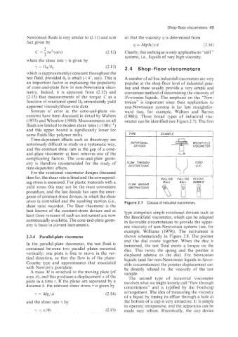
(1975) and Whorlow (1980). Measurements on all ometer can be identified (see Figure 2.7). The first
fluids are limited to modest shear rates (< 100 s-l)
and this upper bound is significantly lower for
some fluids like polymer melts. TYPE 1 EXAMPL€
Time-dependent effects such as thixotropy are
notoriously difficult to study in a systematic way. ROTATIONAL
DEVICES
and the constant shear rate in the gap of a cone- U
and-plate viscometer at least removes one of the
complicating factors. The cone-and-plate geom-
etry is therefore recommended for the study of FLOW THROUGH
time-dependent effects. RESTRICTIONS
For the rotational viscometer designs discussed
thus fa, the shear rate is fixed and the correspond- ROLLING FALLING RISING
ing stress is measured. For plastic materials with a FLOW AROUND BALL BALL BUBBLE
yield stress this may not be the most convenient OBSTRUCTIONS
procedure, and the last decade has seen the emer-
gence of constant-stress devices, in which the shear
stress is ccintrolled and the resulting motion (Le., Figure 2.7 Classes of industrial viscometers
shear rate:i recorded. The Deer rheometer is the
best known of the constant-stress devices and at type comprises simple rotational devices such as
least three versions of such an instrument are now the Brookfield viscometer, which can be adapted
commercially available. The cone-and-plate geom- in favorable circumstances to provide the appar-
etry is basic in current instruments. ent viscosity of non-Newtonian systems (see, for
example, Williams (1979)). The instrument is
2.3.4 Parallel-plate viscometer shown schematically in Figure 2.8. The pointer
and the dial rotate together. When the disc is
In the parallel-plate rheometer, the test fluid is immersed, the test fluid exerts a torque on the
contained between two parallel plates mounted disc. This twists the spring and the pointer is
vertically; one plate is free to move in the ver- displaced relative to the dial. For Newtonian
tical direction, SO that the flow is of the plane- liquids (and for non-Newtonian liquids in favor-
Couette type and approximates that associated able circumstances) the pointer displacement caE
with Newton’s postulate. be directly related to the viscosity of the test
A mass ilid is attached to the moving plate (of sample.
area A), and this produces a displacement x of the The second type of industrial viscometer
plate in a time t. If the plates are separated by a involves what we might loosely call “flow through
distance h, the relevant shear stress T is given by constrictions” and is typified by the Ford-cup
T = Mg/A (2.14) arrangement. The idea of measuring the viscosity
of a liquid by timing its efflux through a hole at
and the shear rate 7 by the bottom of a cup is very attractive. It is simple
to operate, inexpensive, and the apparatus can be
y = x/th (2.15) made very robust. Historically. the cup device