Page 115 - Integrated Wireless Propagation Models
P. 115

M a c r o c e l l   P r e d i c t i o n   M o d e l s -  P a r t   1 :   A r e a - t o - A r e a   M o d e l s    93


                                - 0
                                 1
                                   I
                              m
                              :s.
                               <1>  0                            *',.__. ..... -.
                               ()
                               ctl                          /"
                               Q.                        ;; I
                               (/)
                               <1>                    //
                              �  1 0                ·"'
                               .9                        I
                                            �
                               �          ...--·
                              �      ..- - �      [//
                              �  20  l
                               (/)
                               (/)
                              .2   I
                               c                  I
                               0          7:
                                                  l/
                              � 30
                              ==
                                   / I
                              0
                                 40
                                 -1 .5   -1     -0.5     0     0.5
                                            Normalized clearance h!F1
                                   B:  theoretical knife-edge loss curve
                                   0:  theoretical smooth spherical Earth loss curve,
                                     at 6.5 GHz and k e= 4/3
                                  A d : empirical diffraction loss based on equation
                                     (2) for intermediate terrain
                                   h: amount by which the radio path clears the Earth's
                                     for intermediate terrain
                                  F 1 : radius of the first Fresnel zone
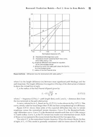
               FIGURE 2.17.2.1  Diffraction loss for obstructed LOS radio pathsY


               where h is the height difference (m) between most significant path blockage and the
                                              h
               path trajectory. The height difference  i s negative if the top of the obstruction of interest
               is above the virtual line of sight.
                  F1 is the radius of the first Fresnel ellipsoid given by

                                            F1  = 17.3�d��2  m                  (2.17.2.2)


               where f = frequency (GHz), d  p ath length (km), and d1 and d 2 = distances (km) from
                                         =
               the two terminals to the path obstruction.
                                                                                  1
                  A curve, referred to as A d , based on Eq. (2.17.2.1), is also shown in Fig. 2.17.2. .   This
               curve, strictly valid for losses larger than 15 dB, has been extrapolated up to 6-dB losses.
                  Figure 2.17.2.1 shows three plots of the expected diffraction loss due to terrain
               roughness versus the normalized terrain clearance. Curve B is the theoretical knife­
               edge diffraction curve. Curve D is the theoretical smooth-earth loss at 6.5 GHz using a
               4/3 earth radius. Curve A d is the ITU terrain loss model over intermediate terrain. Each
               of these curves represents the excess terrain loss beyond the free space loss.
                  The ratio h/F1 is the normalized terrain clearance. When the terrain blocks the line
               of sight, h/ F1 < 0. This model is generally considered valid for losses about 15 dB, but it
   110   111   112   113   114   115   116   117   118   119   120