
Page 111 - Integrated Wireless Propagation Models
P. 111
I
M a c r o c e I P r e d i c t i o n M o d e I s - P a r t 1 : A r e a - t o - A r e a M o d e I s 89
1 0 t- � � -- � � .� :: -- ==== � � � � -�-� .� .: .� . � .. � .� . � .=�1 � :;;= == � �
�
9 / a = 2
8 �----�--------------��------�
1.5
7
6 1.0
"{ "" 5
4 0.5
3
2 0
5 1 0 1 5 20 25 30 35 40 45 50
N u mber of edges n
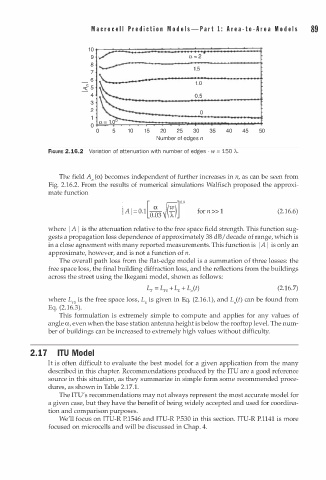
FIGURE 2.16.2 Variation of attenuation with number of edges - w = 150 A.
The field A" (a) becomes independent of further increases in n, as can be seen from
Fig. 2.16.2. From the results of numerical simulations Walfisch proposed the approxi
mate function
for n > > 1 (2.16.6)
where I A I is the attenuation relative to the free space field strength. This function sug
gests a propagation loss dependence of approximately 38 dB I decade of range, which is
in a close agreement with many reported measurements. This function is I A I is only an
approximate, however, and is not a function of n.
The overall path loss from the flat-edge model is a summation of three losses: the
free space loss, the final building diffraction loss, and the reflections from the buildings
across the street using the Ikegami model, shown as follows:
(2.16.7)
where L is the free space loss, L is given in Eq. (2.16.1), and L"(t) can be found from
F5
E
Eq. (2 1 6.3).
.
This formulation is extremely simple to compute and applies for any values of
angle a, even when the base station antenna height is below the rooftop level. The num
ber of buildings can be increased to extremely high values without difficulty.
2.17 ITU Model
It is often difficult to evaluate the best model for a given application from the many
described in this chapter. Recommendations produced by the ITU are a good reference
source in this situation, as they summarize in simple form some recommended proce
dures, as shown in Table 2.17.1.
The ITU's recommendations may not always represent the most accurate model for
a given case, but they have the benefit of being widely accepted and used for coordina
tion and comparison purposes.
We'll focus on ITU-R P.1546 and ITU-R P.530 in this section. ITU-R P.1141 is more
focused on microcells and will be discussed in Chap. 4.