
Page 106 - Integrated Wireless Propagation Models
P. 106
84 C h a p t e r T w o
Transmitter
e
Reflecting
building
_ _
.. ... -
...
T
I
I
I
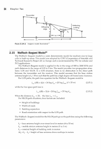
FIGURE 2.14.1 l k egami model illustrated.27
-
a
2.15 Walfisch l k eg m i ModeF8
The Walfisch-Ikegami model is a semi deterministic model for medium-size to large
cells in built-up areas. This model was adopted by COST (Cooperation of Scientific and
Technical Research) Project 231 in Europe and is recommended by ITU for cellular and
PCS applications.
The Walfisch-Ikegami model is applied in the in the range of 800 to 2000 MHz and
path distances in the range of 0.02 to 5 km. The model provides two propagation situa
tions: LOS and NLOS. In a LOS situation, there is no obstruction in the direct path
between the transmitter and the receiver. This model assumes that the base station
antenna height is hb :2: 30 m such that the path has a high degree of Fresnel zone clearance.
For LOS paths, the path loss equation for the Walfisch-Ikegami model is
�1 (dB) = 42.6 + 26 log dkm + 20 logf MHz (d :2: 20 m) (2.15.1)
while the free space path loss is
L (dB) = 32.4 + 20 logf MHz + 20 log dkm (2.15.2)
FS
When the distance dkm ---7 20, the loss L w1 ---7 L rs·
For NLOS path situations, four factors are included:
• Height of buildings
• Width of roads
• Building separation
• Road orientation with respect to the LOS path
The Walfisch-Ikegami model for the NLOS path gives the path loss using the following
parameters:
=
hb b ase antenna height over street level in meters (4 to 50 m)
3
h"' = mobile station antenna height in meters (1 to m )
h8 = nominal height of building roofs in meters
�hb = hb - h8 = height of base antenna above rooftops in meters