
Page 104 - Integrated Wireless Propagation Models
P. 104
82 C h a p t e r T w o
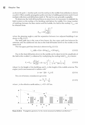
as shown by path . Another path over the rooftop to the mobile from reflection is shown
1
as path 2. Other possible propagation paths exist due to building penetration (path 3) and
multiple reflections and diffractions (path 4). The last two are generally negligible.
To determine the field diffracted down to street level, it is necessary to establish the
field incident on the rooftop of the building right before the mobile. For a large number
of buildings between the base station and the mobile, the field at the rooftop, E Roof ' can
be obtained from
[ ff]0.9
Roof ""
E 0.1 �.� (2.13.1)
0
where the glancing angle a, and the separation between two adjacent buildings b are
1
shown in Fig. 2.13. .
The total path loss is the sum f two losses: the free space path loss between the
o
antennas, and the additional loss due to the final diffraction down to the mobile on the
street level.
The free space path loss formula is shown in Eq. (2.13.2):
LFS (dB) = 32.4 + 20 logJ M Hz + 20 log dkm (2.13.2)
Due to the final diffraction down to the mobile on the street level, the amplitude of
the field at the mobile E, is obtained by multiplying the rooftop field E by a factor:
Roof
(2.13.3)
where h is the height of the buildings and h., is the height of the mobile antenna. The
angles y and a are measured in radians with
1
y = tan- [2(h - h,) I d] (2.13.4)
For a level terrain, a (radians) is given by
h -h d
a= -b _ _ _ (2.13.5)
_
d 2re
where re is the effective earth radius, re = 8.5 x 10³ km.
d
�-----------------------:�
FIGURE 2.13.1 Propagation geometry for the model proposed by Walfisch and Bertoni.24