
Page 107 - Integrated Wireless Propagation Models
P. 107
M a c r o c e l l P r e d i c t i o n M o d e l s - P a r t 1 : A r e a - t o - A r e a M o d e l s 85
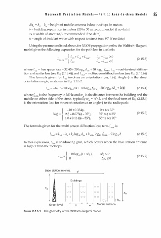
t:.h m = h8 - h m = h eight of mobile antenna below rooftops in meters
=
b b uilding separation in meters (20 to 50 m recommended if no data)
W = width of street (b /2 recommended if no data)
<)> = angle of incident wave with respect to street (use 90° if no data)
Using the parameters listed above, for NLOS propagation paths, the Walfisch-Ikegami
model gives the following expression for the path loss in decibels:
{ L + L,,, + L mds '
FS
L,,, + L mds � Q
[ NLOS = L FS L,,, + [mds < Q (2.15.3)
where L = free space loss = 32.45+20 log 10 dkm + 20 log J MHz L,,, = roof-to-street diffrac
F5
10
'
tion and scatter loss (see Eq. (2.15.4)), and L a = multiscreen diffraction loss (see Eq. (2.15.6)).
ms
The formula given for L,1, involves an orientation loss, L(<)>). Angle <)> is the street
orientation angle, as shown in Fig. 2.15.2.
L,,, = -16.9- 1 0 log 10 W + 10 log 10 fMHz + 20 log 10 t:.h"' + L (<!>) (2.15.4)
wheref z is the frequency in MHz and w is the distance between the building and the
MH
"'
mobile on either side of the street, typically w = W /2, and the final term of Eq. (2.15.4)
,
is the orientation loss for street orientation at an angle <!> to the radio path:
1 -10+ 0.354<)>, 0 :S:: <)> ::; 35°
L(<)>) = 2.5+ 0.075(<)>- 3 5°), 35° ::; ::; 35° (2.15.5)
<!>
<!>
4.0+ 0.114(<)>- 55°), 55° ::; ::; 90°
The formula given for the multi screen diffraction loss term L, s a is
(2.15.6)
In this expression, Lbsh is shadowing gain, which occurs when the base station antenna
is higher than the rooftops:
{ -18log 10 (1+l1hb),
L = (2.15.7)
bsh
0,
Base station antenna d
-
Buildings
r-
- - - --
D D D D D D D D
hb
D D D D D D D D
h a
D D D D D D D D
c Thm
Street level b � Mobile antenna
w
FIGURE 2.15.1 The geometry of the Walfisch-lkega i mode . l
m