
Page 110 - Integrated Wireless Propagation Models
P. 110
88 C h a p t e r T w o
Final building
�
_______L_______·f l l l l l l l l rJi> L
�
t
-.----� :_
r n buildings
-------------------------1�
R
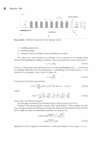
FIGURE 2.16.1 Defin i tion of geometry for the flat-edge modeL
w = building separation
h0 = building height
dm = distance from the mobile to the last building in meters
The value of w used should be an effective way to account for the longer paths
between the buildings for oblique incidence. The excess path loss is then expressed as
(2.16.1)
where Lke is the single-edge diffraction loss over the final building and L" - 1 is the loss
-
for multiple diffraction over the remaining (n 1 ) buildings. The result is that L" 1 is a
-
function of a parameter t only, where t is given by
t =-a v rmv (2.16.2)
T
It is given by the following formula:
1 11-1
2
Lll(t) = n LLn,(t)F , (-jt../n-m) for n 1 Lo(t) = 1 (2.16.3)
m 0
-
where
(2.16.4)
and 5 and C are Fresnel integrals.
.
The flat-edge model may be calculated either directly from Eq. (2 1 6.3).
2
Walfisch 8 has introduced the concept of the "settled field": if the number of build
ing n is large enough for buildings to occupy the whole of the first Fresnel zone from the
line-of-sight ray, then the attenuation function can be given by
(jkwa ) [ rruv ]
2
A"(a) =exp - - L" a VT
2
(jkwa )
2
= exp - - LJt] (2.16.5)
2
Equation (2.16.5) is applied to the distance r to the base station is very large, r >> n w.