
Page 105 - Integrated Wireless Propagation Models
P. 105
M a c r o c e l l P r e d i c t i o n M o d e l s - P a r t 1 : A r e a - t o - A r e a M o d e l s 83
Equation (2.13.3) is further simplified by neglecting / ( 2rc + y- a) as compared to
1
1 / ( y- a) and assuming that a is small compared to y.
.
Using Eqs. (2 1 3.2), (2.13.3), (2.13.4), and (2.13.5), the excess loss is given by
2
L,)dB) = 57.1 A + logfc + 1 l ogd-1 l og(hb -h)-18 l og(1- � ) (2.13.6)
8
8
+
17( b -h)
The last term in Eq. (2.13.6) accounts for the earth curvature. It can often be neglected.
The building geometry A can be expressed as
(2.13.7)
When using isotropic antennas, the total path loss is obtained by adding Lex to the
free space path loss L s ·
F
a
2.14 l k eg m i Mode! 27
The Ikegami model tries to predict the field strengths at each point in an urban coverage
area using a ray-theoretical approach. Ikegami analyzed the controlling propagation
factors based on the geometrical optics assuming a simple two-ray model.
Ikegami has made extensive drive tests in Kyoto City. He analyzed building
heights, shapes, and positions with detailed city maps and traced ray paths between
the transmitter and receiver using only single reflections from the walls of the build
ings. Diffraction is calculated using a single-edge approximation at the building
nearest the mobile unit. The building-wall reflection loss is assumed to be fixed as a
constant value. The two rays, reflected and diffracted, are received by the mobile
unit as follows:
E m = E s -10 log J MHz -10 log (sin<j>)-20 log (hb -h"')
F
1
+ 1 0 l ogW + 1 0 log( + � ) + 5 .8 (2.14.1)
=
where E "' l ocal mean field strength, E 5 f ree space field strength, L, = reflection loss,
=
F
set to a fixed value at -6 dB, <1> = angle between the street and the direct line from base
to mobile, hb = b uilding height in meters, hm =receiver height in meters, W =street width
in meters, and fc = frequency in MHz.
1
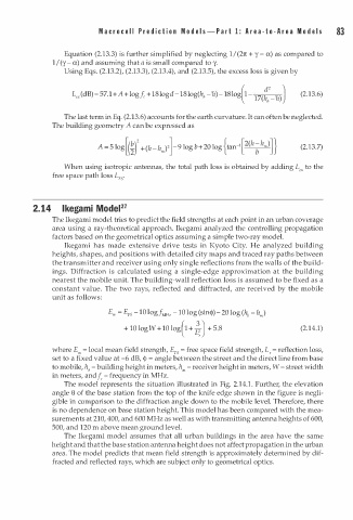
The model represents the situation illustrated in Fig. 2.14. . Further, the elevation
angle e of the base station from the top of the knife edge shown in the figure is negli
gible in comparison to the diffraction angle down to the mobile level. Therefore, there
is no dependence on base station height. This model has been compared with the mea
surements at 210,400, and 600 MHz as well as with transmitting antenna heights of 600,
500, and 120 m above mean ground level.
The Ikegami model assumes that all urban buildings in the area have the same
height and that the base station antenna height does not affect propagation in the urban
area. The model predicts that mean field strength is approximately determined by dif
fracted and reflected rays, which are subject only to geometrical optics.