
Page 123 - Integrated Wireless Propagation Models
P. 123
M a c r o c e I P r e d i c t i o n M o d e I s - P a r t 2 : P o i n t - t o - P o i n t M o d e I s 101
I
• Center frequency, which can be used to further optimized the prediction.
• Path loss slope values per land-use class, for use with the automorphology model.
Sector parameters can be specified for each sector, which include environment type,
the mode of the model to be used, path loss slope(s)/intercept(s), radial length, and
number of radials.
When using the single breakpoint model or the automorphology model, you may
specify a single slope and a 1-mile intercept. When you choose to use the multiple
breakpoint model, you may specify additional slopes and intercepts.
The choice of environment type brings with it the associated values for the model
parameters, such as radial length dx, gain factor, loss factor, and distance from reflection
point and mobile smoothing. This set of parameters is independent of the choice for all
other sector parameters related to macrocell modeling.
All sector parameters may be specified for each sector individually or on a group
basis for any group of cells/sectors.
The model is based on the experimentation that can be created through the terrain
and signal profiles or by including the slope and intercept calculations through mea
surement integration.
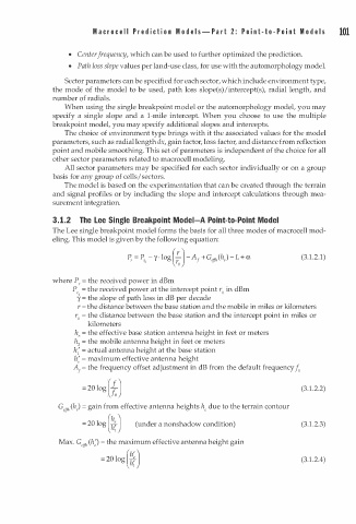
3 . 1 . 2 The Lee Single Breakpoint Model-A Point-to-Point Model
The Lee single breakpoint model forms the basis for all three modes of macrocell mod
eling. This model is given by the following equation:
!...
P , = P , - y · log( ) - A 1 + G (h, ) - L + a (3.1 . 2.1)
efl7
o ro
where P, = the received power in dBm
P = the received power at the intercept point r0 in dBm
y = the slope of path loss in dB per decade
'o
r = the distance between the base station and the mobile in miles or kilometers
r0 = the distance between the base station and the intercept point in miles or
kilometers
h, = the effective base station antenna height in feet or meters
h 2 = the mobile antenna height in feet or meters
h; = actual antenna height at the base station
h: = maximum effective antenna height
A1 = the frequency offset adjustment in dB from the default frequency J 0
= 20 log ({ ) (3 1 .2.2)
.
)
G (h = gain from effective antenna heights he due to the terrain contour
,ff"
= 20 log(�) (under a nonshadow condition) (3.1.2.3)
Max. G,ff1, (h;) = the maximum effective antenna height gain
= 2 0 log(�D (3 1 .2.4)
.