
Page 125 - Integrated Wireless Propagation Models
P. 125
I
M a c r o c e I P r e d i c t i o n M o d e I s - P a r t 2 : P o i n t - t o - P o i n t M o d e I s 103
direct path is not obstructed by the terrain, it has two conditions: LOS path and the
NLOS path. Also, there is a diffraction path that is obstructed by the terrain:
1 . Nonobstructed direct path or LOS path-When a direct path is not obstructed
by any objects between the transmitter and the mobile and the reflected path
from the ground is weak, the free space path loss formula will be used. If the
mobile is very close to the ground, the reflected path from the ground is strong,
and the open area case is considered.
2. NLOS path-When the direct path is obstructed from human-made structures
and trees, common condition in mobile communications, there is a gain or loss
according to the terrain contour along the radial path. The effective antenna
height gain is a significant contributor to the received signal. This gain varies
according to the terrain contour along the radial path. The effective antenna
height gain is represented by GefJh (h) in Eq. (3.1.2.3)
3. Diffraction path-When the direct path is obstructed by the terrain contour
between the transmitter and the mobile, the signal actually incurs a loss due to
terrain-related diffraction. This diffraction loss is designated by symbol L in
Eq. (3.1.2.5).
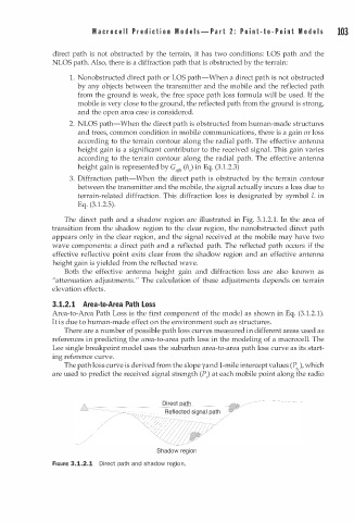
The direct path and a shadow region are illustrated in Fig. 3.1.2.1. In the area of
transition from the shadow region to the clear region, the nonobstructed direct path
appears only in the clear region, and the signal received at the mobile may have two
wave components: a direct path and a reflected path. The reflected path occurs if the
effective reflective point exits clear from the shadow region and an effective antenna
height gain is yielded from the reflected wave.
Both the effective antenna height gain and diffraction loss are also known as
"attenuation adjustments " The calculation of these adjustments depends on terrain
.
elevation effects.
3.1.2. 1 Area-to-Area Path Loss
Area-to-Area Path Loss is the first component of the model as shown in Eq. (3 1 . 2.1).
.
It is due to human-made effect on the environment such as structures.
There are a number of possible path loss curves measured in different areas used as
references in predicting the area-to-area path loss in the modeling of a macrocell. The
Lee single breakpoint model uses the suburban area-to-area path loss curve as its start
ing reference curve.
The path loss curve is derived from the slope y and 1-mile intercept values (P, ), which
,
are used to predict the received signal strength (P,) at each mobile point along the radio
Shadow region
FIGURE 3.1.2.1 Direct path and shadow region.