
Page 409 - Integrated Wireless Propagation Models
P. 409
T h e l e e C o m p r e h e n s i v e M o d e l - I n t e g r a t i o n o f t h e T h r e e l e e M o d e l s 387
These characteristics make underwater wireless communication extremely difficult.
To solve these difficulties, two tools can be used. One is the underwater propagation
path-loss model created by Urick, and another is the propagation speed of the acoustic
signal underwater.
2
6.7. . 1 U r ick Propagation Path-Loss Model
One underwater propagation model, called the Urick propagation path-loss model, is
introduced:
L (d, f ) = � · log (d) + a ( j ) . d + A (6.7.2.1)
where � is the geometric spreading, � = 10 (shallow water); and � = 20 (deep water);
a (j) is medium absorption obtained from the experiments; and A is transmission
anomaly in dB a degradation of acoustic intensity due to multipath refraction, diffrac
A
tion, and scattering of the sound; = 5 to 10 dB [deep water]; > 10 dB [shallow water].
A
6. 7 .2.2 Propagation Speed of Acoustic Signal U n derwater
The propagation speed of the acoustic signal (5) underwater is a function of three
parameters the temperature T, the salinity (Sa), and the depth of the water (D):
j
5 = ( T, Sa, D) (6.7.2.2)
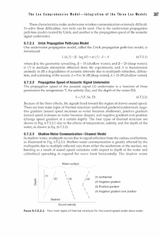
Because of the three effects, the signals bend toward the region of slower sound speed.
There are four main types of thermal structure: isothermal gradient (uniformed), nega
tive gradient (sound speed increases as water becomes shallower), positive gradient
(sound speed increases as water becomes deeper), and negative gradient over position
(change speed gradient at a certain depth). The four types of thermal structure are
shown in Fig. 6.7.2.2.1 due to the effects of temperature, salinity , and the depth of the
water, as shown in Eq. (6.7.2.1).
6. 7 .2.3 Shallow-Water Communication-Channel Model
In shallow water, multi path occurs due to signal reflection from the surface and bottom,
.
as illustrated in Fig. 6.7.2.3 1 . Shallow-water communication is greatly affected by the
multipaths due to multiple reflected rays from either the sea bottom or the surface, ray
bending as a result of sound speed variations with respect to depth of the water and
cylindrical spreading to expand the wave front horizontally. The shadow water
Water surface
I
I
(1) I \ I (1 ) Isothermal
.<: / (2) \ (3) / ( 4)
a. \ (2) Negative gradient
Q) I
0 I (
I (3) Positive gradient
I \ \
I \ \ (4) Negative gradient over positive
I \
I \
Seabed \
Sound velocity
FIGURE 6.7.2.2.1 Fo r main types of thermal structure for the sound speed under deep water.
u