
Page 329 - Intelligent Digital Oil And Gas Fields
P. 329
274 Intelligent Digital Oil and Gas Fields
injection at different time steps (preferably every 4months). This capa-
bility means that the waterfront location between wells can now be esti-
mated and thus water breakthrough can be delayed with high accuracy,
compared with proactive control. The ICV settings can be changed
depending on the waterfront movement. For example, when the water-
front is approaching the wellbore, the ICV in the segment can be
completely off, which maximizes the oil-sweep efficiency. The philos-
ophy is based on trusted 4D seismic processing and interpretation, and
how the 3D numerical model captures the seismic data. Passive control
is the most sophisticated control because it can be used at the right time
with the right tool. However, the use of 4D seismic and this control is
very expensive and requires extensive seismic data and interpretation.
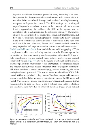
Cullick and Sukkestad (2010) have modeled smart wells by applying ICVs in
complex well architectures including multilaterals wells. They compared the
production performance by using a well completion without an ICV (open-
hole completion), reactive control (fixed policy), and proactive control
(optimized policy). Fig. 7.16 shows the results of different control modes.
The fixed policy is an optimization technique that runs the simulation model
and checks water cut value in each simulation’s time step against the thresh-
old. If the threshold is met or exceeded (e.g., 80% of water cut), the valve
setting is reduced by one unit. The process is continued until the ICV is fully
closed. With the optimized policy, a set of threshold ranges and increment
sets are provided and they are used as optimizer to control the 3D numerical
model. The optimizer seeks a combination of triggers and increments that
maximizes the oil-recovery factor while it reduces both water production
and injection. Each valve has its own best threshold trigger water cut and
Fig. 7.16 Production profiles for no ICV, reactive (fixed policy), and proactive (optimized
policy) controls in a horizontal well with three ICVs. (Taken with permission from SPE
126246.)