
Page 334 - Intelligent Digital Oil And Gas Fields
P. 334
278 Intelligent Digital Oil and Gas Fields
decisions are made for ICV control). The main difference between smart and
traditional IOR/EOR processes is that smart EOR uses:
• Massive subsurface (fiber optic or seismic) data streaming to monitor the
frontal advance of injected fluids (water or steam).
• ICVs to control the well at down-hole condition, which allows better
oil-sweep efficiency by focusing water, steam, or gas in the upswept/
bypassed reservoir segments.
• Coupled surface, wellbore, and 3D reservoir models in simulators to
generate scenarios to prevent early water, steam, or gas breakthrough
to the producer wells.
7.8.1 WAG Injection Process
The WAG process is designed to improve sweep efficiency in order to reduce
residual oil saturation after conventional water or gas injection and to control
early water or gas breakthrough to producer wells. Depending on the fluid and
rock types, viscosity, and wettability, water is injected into the reservoir for
2–6months, followed by gas, and the cycle is repeated. Simultaneous water
and gas (SWAG) injection is a variation where water and gas are injected
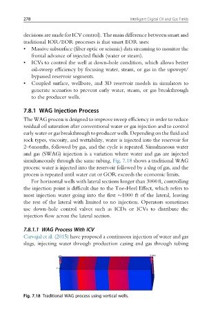
simultaneously through the same tubing. Fig. 7.18 shows a traditional WAG
process: water is injected into the reservoir followed by a slug of gas, and the
process is repeated until water cut or GOR exceeds the economic limits.
For horizontal wells with lateral sections longer than 3000ft, controlling
the injection point is difficult due to the Toe-Heel Effect, which refers to
most injection water going into the first 1000 ft of the lateral, leaving
the rest of the lateral with limited to no injection. Operators sometimes
use down-hole control valves such as ICDs or ICVs to distribute the
injection flow across the lateral section.
7.8.1.1 WAG Process With ICV
Carvajal et al. (2015) have proposed a continuous injection of water and gas
slugs, injecting water through production casing and gas through tubing
Fig. 7.18 Traditional WAG process using vertical wells.