
Page 101 - Intro Predictive Maintenance
P. 101
92 An Introduction to Predictive Maintenance
Rotor passing. The male and female rotors act much like any bladed or gear unit. The
number of lobes on the male rotor multiplied by the actual male shaft speed deter-
mines the rotor-passing frequency. In most cases, there are more lobes on the female
than on the male. To ensure inclusion of all passing frequencies, the rotor-passing fre-
quency of the female shaft also should be calculated. The passing frequency is equal
to the number of lobes on the female rotor multiplied by the actual female shaft speed.
Running speeds. The input, or male, rotor in screw compressors generally rotates at
a no-load speed of either 1,800 or 3,600rpm. The female, or driven, rotor operates at
higher no-load speeds ranging between 3,600 to 9,000rpm. Narrowband windows
should be established to monitor the actual running speed of the male and female
rotors. The windows should have an upper limit equal to the no-load design speed and
a lower limit that captures the slowest, or fully loaded, speed. Generally, the lower
limits are between 15 and 20 percent lower than no-load.
5.3.2 Fans
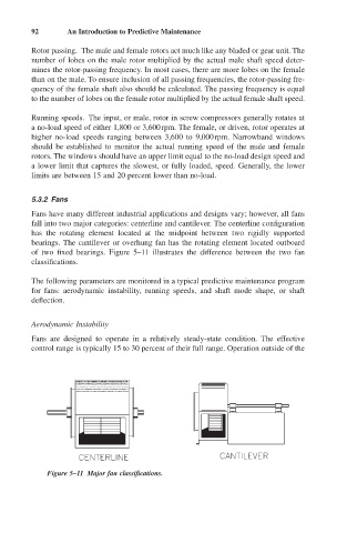
Fans have many different industrial applications and designs vary; however, all fans
fall into two major categories: centerline and cantilever. The centerline configuration
has the rotating element located at the midpoint between two rigidly supported
bearings. The cantilever or overhung fan has the rotating element located outboard
of two fixed bearings. Figure 5–11 illustrates the difference between the two fan
classifications.
The following parameters are monitored in a typical predictive maintenance program
for fans: aerodynamic instability, running speeds, and shaft mode shape, or shaft
deflection.
Aerodynamic Instability
Fans are designed to operate in a relatively steady-state condition. The effective
control range is typically 15 to 30 percent of their full range. Operation outside of the
Figure 5–11 Major fan classifications.