
Page 96 - Intro Predictive Maintenance
P. 96
Machine-Train Monitoring Parameters 87
FIRST-STAGE FIRST-STAGE CONDENSATE
DIFFUSER INTERCOOLER SEPARATOR
SECOND-
FIRST-STAGE STAGE
ROTOR
INLET
FIRST-
STAGE
INLET
BULL- -
GEAR
THIRD-
STAGE
INLET
FOURTH-STAGE
ROTOR
FOURTH-
STAGE
AFTERCOOLER
DISCHARGE INLET
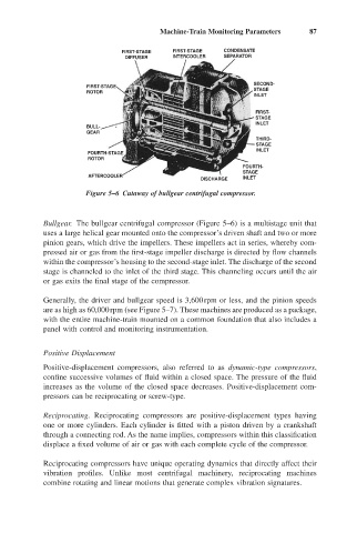
Figure 5–6 Cutaway of bullgear centrifugal compressor.
Bullgear. The bullgear centrifugal compressor (Figure 5–6) is a multistage unit that
uses a large helical gear mounted onto the compressor’s driven shaft and two or more
pinion gears, which drive the impellers. These impellers act in series, whereby com-
pressed air or gas from the first-stage impeller discharge is directed by flow channels
within the compressor’s housing to the second-stage inlet. The discharge of the second
stage is channeled to the inlet of the third stage. This channeling occurs until the air
or gas exits the final stage of the compressor.
Generally, the driver and bullgear speed is 3,600rpm or less, and the pinion speeds
are as high as 60,000rpm (see Figure 5–7). These machines are produced as a package,
with the entire machine-train mounted on a common foundation that also includes a
panel with control and monitoring instrumentation.
Positive Displacement
Positive-displacement compressors, also referred to as dynamic-type compressors,
confine successive volumes of fluid within a closed space. The pressure of the fluid
increases as the volume of the closed space decreases. Positive-displacement com-
pressors can be reciprocating or screw-type.
Reciprocating. Reciprocating compressors are positive-displacement types having
one or more cylinders. Each cylinder is fitted with a piston driven by a crankshaft
through a connecting rod. As the name implies, compressors within this classification
displace a fixed volume of air or gas with each complete cycle of the compressor.
Reciprocating compressors have unique operating dynamics that directly affect their
vibration profiles. Unlike most centrifugal machinery, reciprocating machines
combine rotating and linear motions that generate complex vibration signatures.