
Page 98 - Intro Predictive Maintenance
P. 98
Machine-Train Monitoring Parameters 89
Suction Stroke Compression Stroke
Suction Discharge
Valve Valve
A
Clearance Space Expansion B Suction C Compression D Delivery or Discharge E
Piston at Top
Dead Center Piston at Bottom
Dead Center
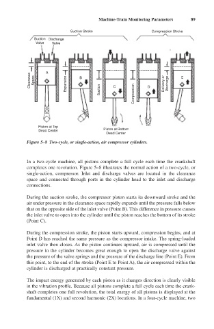
Figure 5–8 Two-cycle, or single-action, air compressor cylinders.
In a two-cycle machine, all pistons complete a full cycle each time the crankshaft
completes one revolution. Figure 5–8 illustrates the normal action of a two-cycle, or
single-action, compressor. Inlet and discharge valves are located in the clearance
space and connected through ports in the cylinder head to the inlet and discharge
connections.
During the suction stroke, the compressor piston starts its downward stroke and the
air under pressure in the clearance space rapidly expands until the pressure falls below
that on the opposite side of the inlet valve (Point B). This difference in pressure causes
the inlet valve to open into the cylinder until the piston reaches the bottom of its stroke
(Point C).
During the compression stroke, the piston starts upward, compression begins, and at
Point D has reached the same pressure as the compressor intake. The spring-loaded
inlet valve then closes. As the piston continues upward, air is compressed until the
pressure in the cylinder becomes great enough to open the discharge valve against
the pressure of the valve springs and the pressure of the discharge line (Point E). From
this point, to the end of the stroke (Point E to Point A), the air compressed within the
cylinder is discharged at practically constant pressure.
The impact energy generated by each piston as it changes direction is clearly visible
in the vibration profile. Because all pistons complete a full cycle each time the crank-
shaft completes one full revolution, the total energy of all pistons is displayed at the
fundamental (1X) and second harmonic (2X) locations. In a four-cycle machine, two