
Page 300 - Intro Predictive Maintenance
P. 300
Failure-Mode Analysis 291
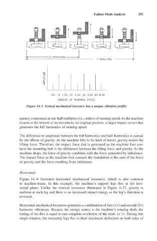
Figure 14–3 Vertical mechanical looseness has a unique vibration profile.
quency component at one-half multiples (i.e., orders) of running speed. As the machine
returns to the bottom of its movement, its original position, a larger impact occurs that
generates the full harmonics of running speed.
The difference in amplitude between the full harmonics and half-harmonics is caused
by the effects of gravity. As the machine lifts to its limit of travel, gravity resists the
lifting force. Therefore, the impact force that is generated as the machine foot con-
tacts the mounting bolt is the difference between the lifting force and gravity. As the
machine drops, the force of gravity combines with the force generated by imbalance.
The impact force as the machine foot contacts the foundation is the sum of the force
of gravity and the force resulting from imbalance.
Horizontal
Figure 14–4 illustrates horizontal mechanical looseness, which is also common
to machine-trains. In this example, the machine’s support legs flex in the hori-
zontal plane. Unlike the vertical looseness illustrated in Figure 4–37, gravity is
uniform at each leg and there is no increased impact energy as the leg’s direction is
reversed.
Horizontal mechanical looseness generates a combination of first (1¥) and second (2¥)
harmonic vibrations. Because the energy source is the machine’s rotating shaft, the
timing of the flex is equal to one complete revolution of the shaft, or 1¥. During this
single rotation, the mounting legs flex to their maximum deflection on both sides of