
Page 330 - Intro Predictive Maintenance
P. 330
Failure-Mode Analysis 321
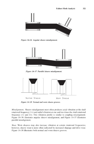
Figure 14–36 Angular sheave misalignment.
Figure 14–37 Parallel sheave misalignment.
Figure 14–38 Normal and worn sheave grooves.
Misalignment. Sheave misalignment most often produces axial vibration at the shaft
rotational frequency (1¥) and radial vibration at one and two times the shaft rotational
frequency (1¥ and 2¥). This vibration profile is similar to coupling misalignment.
Figure 14–36 illustrates angular sheave misalignment, and Figure 14–37 illustrates
parallel misalignment.
Wear. Worn sheaves may also increase vibration at certain rotational frequencies;
however, sheave wear is more often indicated by increased slippage and drive wear.
Figure 14–38 illustrates both normal and worn sheave grooves.