
Page 192 - Introduction to AI Robotics
P. 192
5.5 Assemblages of Behaviors
range far time-remaining 175
time-elapsed
move-
follow-
line ahead
range near
a.
M : K = ffollow-line, move-aheadg, frange near, range farg, =
s =follow-line, F = ffollow-line, move-aheadg
q (q ;
)
follow-line range near move-ahead
follow-line range far follow-line
move-ahead time remaining move-ahead
move-ahead time elapsed follow-line
b.
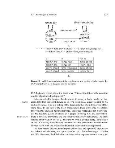
Figure 5.8 A FSA representation of the coordination and control of behaviors in the
UGV competition: a.) a diagram and b.) the table.
FSA, but each works about the same way. This section follows the notation
used in algorithm development. 86
To begin with, the designer has to be able to specify a finite number of dis-
STATES crete states that the robot should be in. The set of states is represented by K,
and each state, q 2 K is a listing of the behaviors that should be active at the
same time. In the case of the UGR competition, there were only two states:
following the line and moving forward. States are represented in a table un-
der the heading q, and by circles in a graph. (See Fig. 5.8.) By convention,
START STATE there is always a Start state, and the robot would always start there. The Start
state is often written as s or q o and drawn with a double circle. In the case
of the UGR entry, the following-line state was the start state since the robot
always starts with the follow-line behavior active and not suppressed.
The next part of the FSA is the inputs (also called the alphabet). Inputs are
the behavioral releasers, and appear under the column heading . Unlike
the IRM diagrams, the FSM table considers what happens to each state q for