
Page 88 - Introduction to Autonomous Mobile Robots
P. 88
Mobile Robot Kinematics
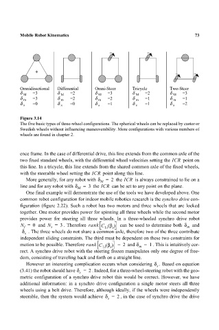
Omnidirectional Differential Omni-Steer Tricycle Two-Steer 73
δ M =3 δ M =2 δ M =3 δ M =2 δ M =3
δ =3 δ =2 δ =2 δ =1 δ =1
m
m
m
m
m
δ =0 δ =0 δ =1 δ =1 δ =2
s s s s s
Figure 3.14
The five basic types of three-wheel configurations. The spherical wheels can be replaced by castor or
Swedish wheels without influencing maneuverability. More configurations with various numbers of
wheels are found in chapter 2.
ence frame. In the case of differential drive, this line extends from the common axle of the
two fixed standard wheels, with the differential wheel velocities setting the ICR point on
this line. In a tricycle, this line extends from the shared common axle of the fixed wheels,
with the steerable wheel setting the ICR point along this line.
More generally, for any robot with δ M = 2 the ICR is always constrained to lie on a
line and for any robot with δ M = 3 the ICR can be set to any point on the plane.
One final example will demonstrate the use of the tools we have developed above. One
common robot configuration for indoor mobile robotics research is the synchro drive con-
figuration (figure 2.22). Such a robot has two motors and three wheels that are locked
together. One motor provides power for spinning all three wheels while the second motor
provides power for steering all three wheels. In a three-wheeled synchro drive robot
β
N = 0 and N = 3 . Therefore rank C () can be used to determine both δ m and
f
s
s
1s
δ s . The three wheels do not share a common axle, therefore two of the three contribute
independent sliding constraints. The third must be dependent on these two constraints for
β
motion to be possible. Therefore rank C () = 2 and δ = 1 . This is intuitively cor-
1s s m
rect. A synchro drive robot with the steering frozen manipulates only one degree of free-
dom, consisting of traveling back and forth on a straight line.
However an interesting complication occurs when considering δ s . Based on equation
(3.41) the robot should have δ = 2 . Indeed, for a three-wheel-steering robot with the geo-
s
metric configuration of a synchro drive robot this would be correct. However, we have
additional information: in a synchro drive configuration a single motor steers all three
wheels using a belt drive. Therefore, although ideally, if the wheels were independently
steerable, then the system would achieve δ = 2 , in the case of synchro drive the drive
s