
Page 83 - Introduction to Autonomous Mobile Robots
P. 83
68
w Chapter 3
1
w 2
a) b)
ICR ICR
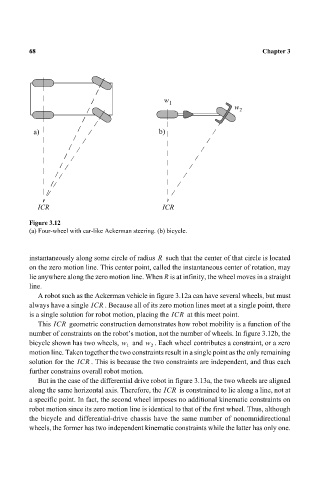
Figure 3.12
(a) Four-wheel with car-like Ackerman steering. (b) bicycle.
R
instantaneously along some circle of radius such that the center of that circle is located
on the zero motion line. This center point, called the instantaneous center of rotation, may
lie anywhere along the zero motion line. When R is at infinity, the wheel moves in a straight
line.
A robot such as the Ackerman vehicle in figure 3.12a can have several wheels, but must
always have a single ICR . Because all of its zero motion lines meet at a single point, there
is a single solution for robot motion, placing the ICR at this meet point.
This ICR geometric construction demonstrates how robot mobility is a function of the
number of constraints on the robot’s motion, not the number of wheels. In figure 3.12b, the
bicycle shown has two wheels, w and w . Each wheel contributes a constraint, or a zero
1 2
motion line. Taken together the two constraints result in a single point as the only remaining
solution for the ICR . This is because the two constraints are independent, and thus each
further constrains overall robot motion.
But in the case of the differential drive robot in figure 3.13a, the two wheels are aligned
along the same horizontal axis. Therefore, the ICR is constrained to lie along a line, not at
a specific point. In fact, the second wheel imposes no additional kinematic constraints on
robot motion since its zero motion line is identical to that of the first wheel. Thus, although
the bicycle and differential-drive chassis have the same number of nonomnidirectional
wheels, the former has two independent kinematic constraints while the latter has only one.