
Page 203 - Introduction to Colloid and Surface Chemistry
P. 203
192 Charged interfaces
the cell wall. For a flat cell the 'stationary levels' are located at
fractions of about 0.2 and 0.8 of the total depth, the exact locations
depending on the width/depth ratio. If the particle and cell surfaces
have the same zeta potential, the velocity of particles at the centre of
the cell is twice their true electrophoretic velocity in a cylindrical cell
and 1.5 times their true electrophoretic velocity in a flat cell.
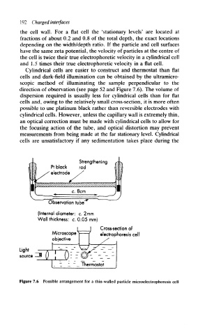
Cylindrical cells are easier to construct and thermostat than flat
cells and dark-field illumination can be obtained by the ultramicro-
scopic method of illuminating the sample perpendicular to the
direction of observation (see page 52 and Figure 7.6). The volume of
dispersion required is usually less for cylindrical cells than for flat
cells and, owing to the relatively small cross-section, it is more often
possible to use platinum black rather than reversible electrodes with
cylindrical cells. However, unless the capillary wall is extremely thin,
an optical correction must be made with cylindrical cells to allow for
the focusing action of the tube, and optical distortion may prevent
measurements from being made at the far stationary level. Cylindrical
cells are unsatisfactory if any sedimentation takes place during the
Strengthening
Pt black rod
electrode
c. 8cm
Observation tube
(Internal diameter: c. 2mm
Wall thickness: c. 0.05 mm)
Cross-section of
Microscope electrophoresis eel
objective
Light
source
Figure 7.6 Possible arrangement for a thin-walled particle microelectrophoresis cell