
Page 173 - Introduction to Information Optics
P. 173
158 2. Signal Processing with Optics
e s
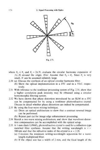
Fig. 2.71.
where 6 0 ^ (9 S and 6 S — 2n/N, evaluate the circular harmonic expansion of
/(r, 6) around the origin. Hint: Assume that 6> 0 = O s. Since 0, is very
small, N can be assumed infinitely large.
2.30 (a) Discuss the synthesis of an optical circular harmonic filter.
(b) Show the optical implementation in a JTC and in a VLC, respec-
tively.
2.31 With reference to the nonlinear processing system of Fig. 2.31, show that
a higher correlation peak intensity may be obtained using a circular
homomorphic filtering system.
2.32 We have shown that phase distortion introduced by an SLM in a JTC
can be compensated for by using a nonlinear photorefractive crystal.
Discuss in detail whether phase distortion can indeed be compensated.
2.33 By using the four-wave mixing technique,
(a) Draw an optical architecture to show that a contrast reversal image
can be performed.
(b) Repeat part (a) for image edge enhancement processing.
2.34 Sketch a two-wave mixing architecture, and show that wavefront-distor-
tion compensation can be accomplished with the optical setup.
2.35 A 1-mm-thick LiNbO 3 photorefractive crystal is used for a reflection-type
matched filter synthesis. Assume that the writing wavelength is A =
500 nm and that the refractive index of the crystal is n — 2.28.
(a) Calculate the minimum writing-wavelength separation for a wave-
length-multiplexed filter.
(b) If the object size has a width of 2 mm, and the focal length of the