
Page 212 - Introduction to Information Optics
P. 212
3.4. Fiber-Optic Networks 1.97
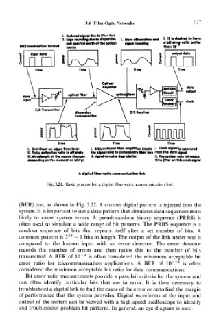
I. Reduced signal due to fiber toss
II. Edge rounding due to dispersion |. More attenuation and «• It Is d**ir«l to now
.. . , . and spectralwidth of the optical tlgnal rounding a bit *ror ratio bottw
NR2 modulation format f «,rce than If *
output ilatci
Time TtllM Tlnw
I. Overshoot on edges from loser I. Erbium-doped fiber i its I. Clack signal Is recovered
II. Finite extinction ratio In off state the signal level to compensate fiber loss from the data signal
III .Wavelength of the source changes II. ilgnol-to-no)se degradation II. the system may Introduce
depending on the modulation (chirp) time fitter on this clock signal
A digital fiber-optic communication link
Fig. 3.21. Basic process for a digital fiber-optic communication link.
(BER) test, as shown in Fig. 3.22. A custom digital pattern is injected into the
system. It is important to use a data pattern that simulates data sequences most
likely to cause system errors. A pseudorandom binary sequence (PRBS) is
often used to simulate a wide range of bit patterns. The PRBS sequence is a
random sequence of bits that repeats itself after a set number of bits. A
23
common pattern is 2 — 1 bits in length. The output of the link under test is
compared to the known input with an error detector. The error detector
records the number of errors and then ratios this to the number of bits
9
transmitted. A BER of 10~ is often considered the minimum acceptable bit
13
error ratio for telecommunication applications. A BER of 1CT is often
considered the minimum acceptable bit ratio for data communications.
Bit error ratio measurements provide a pass/fail criteria for the system and
can often identify particular bits that are in error. It is then necessary to
troubleshoot a digital link to find the cause of the error or onto find the margin
of performance that the system provides. Digital waveforms at the input and
output of the system can be viewed with a high-speed oscilloscope to identify
and troubleshoot problem bit patterns. In general, an eye diagram is used.