
Page 222 - Introduction to Information Optics
P. 222
Vv'~?
4.2. All-Optical Switches it) /
lout A
lin
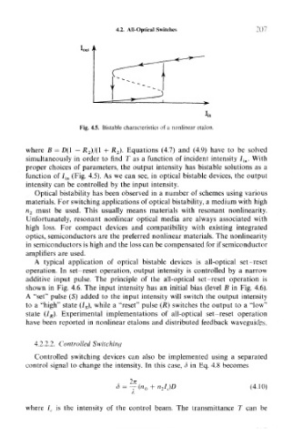
Fig. 4.5. Bistable characteristics of a nonlinear etalon.
where B = £>(! - # 2)/0 + #2)- Equations (4.7) and (4.9) have to be solved
simultaneously in order to find T as a function of incident intensity / in . With
proper choices of parameters, the output intensity has bistable solutions as a
function of 7 jn (Fig. 4.5). As we can see, in optical bistable devices, the output
intensity can be controlled by the input intensity.
Optical bistability has been observed in a number of schemes using various
materials. For switching applications of optical bistability, a medium with high
n 2 must be used. This usually means materials with resonant nonlinearity.
Unfortunately, resonant nonlinear optical media are always associated with
high loss. For compact devices and compatibility with existing integrated
optics, semiconductors are the preferred nonlinear materials. The nonlinearity
in semiconductors is high and the loss can be compensated for if semiconductor
amplifiers are used.
A typical application of optical bistable devices is all-optical set-reset
operation. In set-reset operation, output intensity is controlled by a narrow
additive input pulse. The principle of the all-optical set-reset operation is
shown in Fig. 4.6. The input intensity has an initial bias (level B in Fig. 4.6).
A "set" pulse (S) added to the input intensity will switch the output intensity
to a "high" state (/ s), while a "reset" pulse (R) switches the output to a "low"
state (I R). Experimental implementations of all-optical set-reset operation
have been reported in nonlinear etalons and distributed feedback waveguides.
4.2.2.2. Controlled Switching
Controlled switching devices can also be implemented using a separated
control signal to change the intensity. In this case, o in Eq. 4.8 becomes
8 = —(n 0 + n 2I c)D (4.10)
where l c is the intensity of the control beam. The transmittance T can be