
Page 223 - Introduction to Information Optics
P. 223
208 4. Switching with Optics
::::FT.ln
Time
I in
Fig. 4.6. Set-rest operation in an optically bistable system.
controlled by the control intensity I c. The required amount of change in d for
switching depends on the linewidth of the transmission peak.
The control signal should be at a different wavelength or polarization, or
different incident angle from the data signal, such that it can be separated from
the data signal at the output.
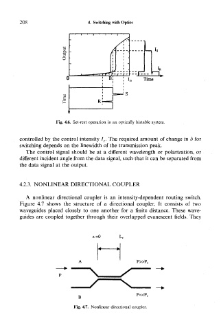
4.2.3. NONLINEAR DIRECTIONAL COUPLER
A nonlinear directional coupler is an intensity-dependent routing switch.
Figure 4.7 shows the structure of a directional coupler. It consists of two
waveguides placed closely to one another for a finite distance. These wave-
guides are coupled together through their overlapped evanescent fields. They
z =0
P»Pc
B P«Pc
Fig. 4.7. Nonlinear directional coupler.