
Page 244 - Introduction to Information Optics
P. 244
4.3. Fast Electro-optic Switches: Modulators
Waveguide Tmmmmon line
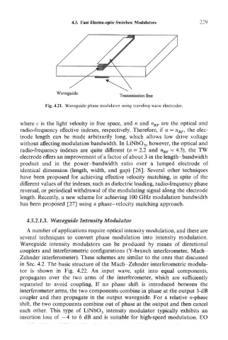
Fig. 4.21. Waveguide phase modulator using traveling wave electrodes.
where c is the light velocity in free space, and n and n RF are the optical and
radio-frequency effective indexes, respectively. Therefore, if n = n RF, the elec-
trode length can be made arbitrarily long, which allows low drive voltage
without affecting modulation bandwidth. In LiNbO 3, however, the optical and
radio-frequency indexes are quite different (n = 2.2 and n RF - 4.3), the TW
electrode offers an improvement of a factor of about 3 in the length-band width
product and in the power-bandwidth ratio over a lumped electrode of
identical dimension (length, width, and gap) [26]. Several other techniques
have been proposed for achieving effective velocity matching, in spite of the
different values of the indexes, such as dielectric loading, radio-frequency phase
reversal, or periodical withdrawal of the modulating signal along the electrode
length. Recently, a new scheme for achieving 100 GHz modulation bandwidth
has been proposed [27] using a phase-velocity matching approach.
4.3.2.1.3. Waveguide Intensity Modulator
A number of applications require optical intensity modulation, and there are
several techniques to convert phase modulation into intensity modulation.
Waveguide intensity modulators can be produced by means of directional
couplers and interferometric configurations (Y-branch interferometer, Mach-
Zehnder interferometer). These schemes are similar to the ones that discussed
in Sec. 4.2. The basic structure of the Mach-Zehnder interferometric modula-
tor is shown in Fig. 4.22. An input wave, split into equal components,
propagates over the two arms of the interferometer, which are sufficiently
separated to avoid coupling. If no phase shift is introduced between the
interferometer arms, the two components combine in phase at the output 3-dB
coupler and then propagate in the output waveguide. For a relative 7t-phase
shift, the two components combine out of phase at the output and then cancel
each other. This type of LiNbO 3 intensity modulator typically exhibits an
insertion loss of —4 to 6 dB and is suitable for high-speed modulation. EO