
Page 371 - Introduction to Information Optics
P. 371
356 7. Pattern Recognition with Optics
7.1. BASIC ARCHITECTURES
7.1.1. CORRELATORS
In terms of correlation detection, optical implementation for pattern recog-
nition can be accomplished either by using Fourier-domain complex matched
filtering or spatial-domain filtering. Correlators that use Fourier-domain
matched filtering are commonly known as VLCs contrast to spatial-domain
filtering in the JTC. The basic distinction between them is that the VLC
depends on Fourier-domain spatial filter synthesis (e.g., Fourier hologram),
whereas the JTC depends on spatial-domain (impulse-response) filter synthesis.
In other words, the complex spatial detection of the Vander Lugt arrangement
is input scene independent, while the joint-transform method is input scene
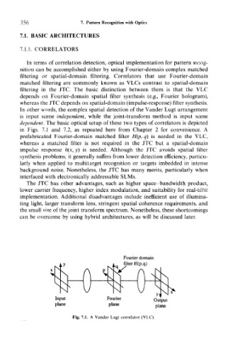
dependent. The basic optical setup of these two types of correlators is depicted
in Figs. 7.1 and 7.2, as repeated here from Chapter 2 for convenience. A
prefabricated Fourier-domain matched filter H(p, q) is needed in the VLC,
whereas a matched filter is not required in the JTC but a spatial-domain
impulse response h(x, y) is needed. Although the JTC avoids spatial filter
synthesis problems, it generally suffers from lower detection efficiency, particu-
larly when applied to multitarget recognition or targets imbedded in intense
background noise. Nonetheless, the JTC has many merits, particularly when
interfaced with electronically addressable SLMs.
The JTC has other advantages, such as higher space-bandwidth product,
lower carrier frequency, higher index modulation, and suitability for real-time
implementation. Additional disadvantages include inefficient use of illumina-
ting light, larger transform lens, stringent spatial coherence requirements, and
the small size of the joint transform spectrum. Nonetheless, these shortcomings
can be overcome by using hybrid architectures, as will be discussed later.
Fourier domain
iq filter H(p,q)
N. '
\ X
A \
* 1 X^^
]
1— \
\ S U
y\ N
j i
Input Fourier Output
plane plane plane
Fig. 7.1. A Vander Lugt correlator (VLC).