
Page 375 - Introduction to Information Optics
P. 375
360 7. Pattern Recognition with Optics
LCTV1
Incoherent <& Lenslet Imaging
Light Source Diffuser Array Lens
LCTV2 CC0
Camera
OD-
'• \
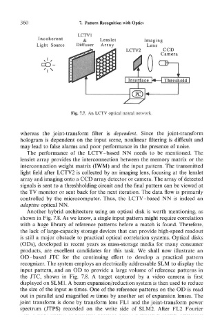
Fig. 7.7. An LCTV optical neural network.
whereas the joint-transform filter is dependent. Since the joint-transform
hologram is dependent on the input scene, nonlinear filtering is difficult and
may lead to false alarms and poor performance in the presence of noise.
The performance of the LCTV-based NN needs to be mentioned. The
lenslet array provides the interconnection between the memory matrix or the
interconnection weight matrix (IWM) and the input pattern. The transmitted
light field after LCTV2 is collected by an imaging lens, focusing at the lenslet
array and imaging onto a CCD array detector or camera. The array of detected
signals is sent to a threshholding circuit and the final pattern can be viewed at
the TV monitor or sent back for the next iteration. The data flow is primarily
controlled by the microcomputer. Thus, the LCTV-based NN is indeed an
adaptive optical NN.
Another hybrid architecture using an optical disk is worth mentioning, as
shown in Fig. 7.8. As we know, a single input pattern might require correlation
with a huge library of reference patterns before a match is found. Therefore,
the lack of large-capacity storage devices that can provide high-speed readout
is still a major obstacle to practical optical correlation systems. Optical disks
(ODs), developed in recent years as mass-storage media for many consumer
products, are excellent candidates for this task. We shall now illustrate an
OD- based JTC for the continuing effort to develop a practical pattern
recognizer. The system employs an electrically addressable SLM to display the
input pattern, and an OD to provide a large volume of reference patterns in
the JTC, shown in Fig. 7.8. A target captured by a video camera is first
displayed on SLM1. A beam expansion/reduction system is then used to reduce
the size of the input m times. One of the reference patterns on the OD is read
out in parallel and magnified m times by another set of expansion lenses. The
joint transform is done by transform lens FL1 and the joint-transform power
spectrum (JTPS) recorded on the write side of SLM2. After FL2 Fourier