
Page 366 - Introduction to Information Optics
P. 366
Exercises 351
6.4! Y. Li, J. Fopelek, L. J. Wang, Y. Takiguchi, T. Wang, and K. Shum "Clock Delivery Using
Laminated Polymer Fiber Circuits," J. Opt. A: Pure and Appl. Opt., vol. 1, pp. 239 243.
6.42 Y. Li, T. Wang, J.-K. Rhee, and L. J. Wang, 1998, "Multigigabits per Second Board-Level
Clock Distribution Schemes Using Laminated End-Tapered Fiber Bundles," IEEE Photonics
Tech. Lett., vol. 10, pp. 884-886.
6.43 Y. Li and T. Wang, 1996, "Distribution of Light Power and Optical Signals Using Embedded
Mirrors Inside Polymer Optical Fibers," IEEE Photonics Tech. Lett., vol. 8, pp. 1352 1354.
6.44 P. Sweazey, "Limits of Performance of Backplane Buses," in Digital Bus Handbook, J. De
Giacomo, Ed., McGraw-Hill, New York, 1990.
6.45 Ray T. Chen, 1994, "VME Optical Backplane Bus for High Performance Computer," Jpn. J.
Optoeicc. Dev. Tech., vol.9, pp. 81-94.
EXERCISES
6.1 Explain why single mode waveguides can support high-speed optical
signals over longer length as compared to multimode waveguides.
6.2 What are the factors limiting the transmission speed in an optoelectronic
interconnect? In your opinion, which are most crucial and why?
6.3 What is the phase-matching condition in the context of waveguide grating
couplers?
(a) Show the phase matching in grating couplers with tilted grating
profile.
(b) What do you expect if the gratings are not tilted?
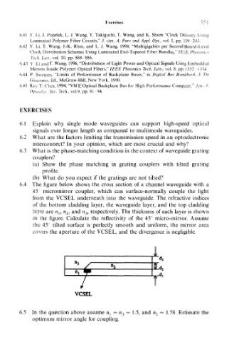
6.4 The figure below shows the cross section of a channel waveguide with a
45 micromirror coupler, which can surface-normally couple the light
from the VCSEL underneath into the waveguide. The refractive indices
of the bottom cladding layer, the waveguide layer, and the top cladding
layer are n 1? n 2, and n 3, respectively. The thickness of each layer is shown
in the figure. Calculate the reflectivity of the 45° micro-mirror. Assume
the 45° tilted surface is perfectly smooth and uniform, the mirror area
covers the aperture of the VCSEL, and the divergence is negligible.
i
14,
A
VCSEL
6.5 In the question above assume n { — n^ = 1.5, and n 2 — 1.58. Estimate the
optimum mirror angle for coupling.