
Page 361 - Introduction to Information Optics
P. 361
346 6. Interconnection with Optics
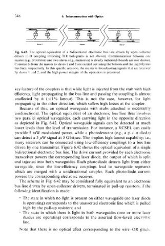
Fig. 6.42. The optical equivalent of a bidirectional electronic bus line driven by open-collector
drivers (3-D coupling involving TIR holograms is not shown). Communication between one
master (e.g., processor) and two slaves (e.g., memories) is clearly indicated (boards are not shown).
Commands from the master to slaves 1 and 2 are carried out using the bottom and the top polymer
bus lines, respectively. In this specific scenario, the master is broadcasting signals that are received
by slaves 1 and 2, and the high power margin of the operation is preserved.
key feature of the couplers is that while light is injected from the stub with high
efficiency, light propagating in the bus line and passing the coupling is almost
unaffected by it (<1% fanout). This is not the case, however, for light
propagating in the other direction, which suffers high losses at the coupler.
Because of this, an optical waveguide with stubs attached is necessarily
unidirectional. The optical equivalent of an electronic bus line thus involves
two parallel optical waveguides, each carrying light in the opposite direction
as depicted in Fig. 6.42. Optical waveguide signals can be detected at much
lower levels than the level of transmission. For instance, a VCSEL can easily
provide 5 mW modulated power, while a photodetector (e.g., a p-i-n diode)
can detect a 5 ^W signal at 5 Gbit/sec. This implies high fanout capability; i.e.,
many receivers can be connected using low-efficiency couplings to a bus line
driven by one transmitter. Figure 6.42 shows the optical equivalent of a single
bidirectional electronic bus line. The drive current provided by each electronic
transceiver powers the corresponding laser diode, the output of which is split
and injected into both waveguides. Each photodiode detects light from either
waveguide, since the low-efficiency couplings lead to waveguide segments
which are merged with a unidirectional coupler. Each photodiode current
powers the corresponding electronic receiver.
The scheme in Fig. 6.42 may be considered fully equivalent to an electronic
bus line driven by open-collector drivers, terminated in pull-up resistors, if the
following identification is made:
* The state in which no light is present on either waveguide (no laser diode
is operating) corresponds to the unasserted electronic line which is pulled
high by the pull-up resistors; and
* The state in which there is light in both waveguides (one or more laser
diodes are operating) corresponds to the asserted (low-level) electronic
line.
Note that there is no optical effect corresponding to the wire-OR glitch.