
Page 362 - Introduction to Information Optics
P. 362
6.7. Polymer Waveguide-Based Optical Bus Structure 347
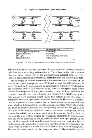
Optical Bus State Tri-State Logic State
Light in Upper Waveguide Pair Asserted High
Light in Lower Pair Asserted Low
No Light Disconnected (High Impedance)
Light in Both Pairs No Equivalent
Fig. 6.43. The optical equivalent of tristate bidirectional electronic bus line.
When two diodes are on, and one turns off, every detector continues to receive
light from the other as long as it remains on. This is because the optical powers
from two diodes simply add in the waveguide; any detected nonzero power
(above a characteristic noise threshold) corresponds to the asserted line state.
The analogue to resistive transmission line termination is treatment of the
ends of the optical waveguides on a PC board so that the reflected power is
zero. This is done by implementing an antireflection coating or by fabricating
the waveguide ends at the Brewster angle, with an absorptive beam dump
outside the waveguides. If this optical isolation is done, settling-time effects are
removed. Note that the optical bus line just described has exactly two states:
light present (low) and light absent (high). This suffices, as just described, to
represent a two-state open-collector-driven line exactly. However, it is insuffi-
cient to represent a tristate-driven line: a tristate driver has an asserted-high
state, which is distinguishable from the disconnected state. Where the tristate
line must be exactly emulated, the corresponding optical bus line can consist
of a pair of the lines just described, that is, four optical waveguides, with a
separate laser diode and a separate photodiode for each pair (see Fig. 6.43). In
this case, the state with no light in any waveguide represents the disconnected
state (no device asserting) as before, while the state with light present in the
top pair (for example) indicates the asserted-high state, and that with light in
the lower pair, the asserted-low state. Note that this scheme overrepresents the
tristate line, as there is a fourth state with light in both pairs of waveguides.
The optoelectronic circuit can be integrated into a fully embedded optical