
Page 394 - Introduction to Information Optics
P. 394
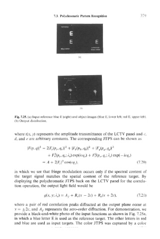
7.3. Polychromatic Pattern Recognition


       Fig. 7.25. (a) Input reference blue E (right) and object images (blue E, lower left; red E. upper left).
       (b) Output distribution.


       where t(x, y) represents the amplitude transmittance of the LCTV panel and r,
       d, and e are arbitrary constants. The corresponding JTPS can be shown as

                                 2
                    2
                 , q}\  = 2|F r (p r ,<? P )|  + \F b(p b,q b)\ 2  \F g(p gtq g)\ 2
                           2
                        + F (p f, q r- A r) exp(icq r) +  2 (p r, q r\ A r) exp(- icq,.)
                              2
                     = A + 2F r| cos(cY/,.),                         (7.20)
       in which we see that fringe modulation occurs only if the spectral content of
       the target signal matches the spatial content of the reference target. By
       displaying the polychromatic JTPS back on the LCTV panel for the correla-
       tion operation, the output light field would be

                              = A f + R r(x - 2c) + R r(x + 2c),     (7.21)

       where a pair of red correlation peaks diffracted at the output plane occur at
       x = ± 2c, and A f represents the zero-order diffraction. For demonstration, we
       provide a black-and-white photo of the input functions as shown in Fig. 7.25a,
       in which a blue letter E is used as the reference target. The other letters in red
       and blue are used as input targets. The color JTPS was captured by a color