
Page 589 - Introduction to Information Optics
P. 589
574 10. Sensing with Optics
Light source
directional
coupler
Movable
mirror
Fig. 10.2. Intensity-type fiber-optic sensor based on reflection.
suitable reference signal is usually added in this type of intensity-based
>er-optic sensor.
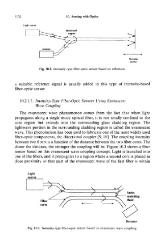
10.2.1.3. Intensity-Type Fiber-Optic Sensors Using Evanescent
Wave Coupling
The evanescent wave phenomenon comes from the fact that when light
propagates along a single mode optical fiber, it is not totally confined to the
core region but extends into the surrounding glass cladding region. The
lightwave portion in the surrounding cladding region is called the evanescent
wave. This phenomenon has been used to fabricate one of the most widely used
fiber-optic components, the directional coupler [9,10]. The coupling intensity
between two fibers is a function of the distance between the two fiber cores. The
closer the distance, the stronger the coupling will be. Figure 10.3 shows a fiber
sensor based on this evanescent wave coupling concept. Light is launched into
one of the fibers, and it propagates to a region where a second core is placed in
close proximity so that part of the evanescent wave of the first fiber is within
Index
matching
Fiber fluid
cores
Detector
Fig. 10.3. Intensity-type fiber-optic sensor based on evanescent wave coupling.